Camille Bauer SINEAX CAM Gebruiksaanwijzing - Pagina 10
Blader online of download pdf Gebruiksaanwijzing voor {categorie_naam} Camille Bauer SINEAX CAM. Camille Bauer SINEAX CAM 12 pagina's. Graphic display for sineax cam
Ook voor Camille Bauer SINEAX CAM: Gebruiksaanwijzing (19 pagina's)

7.2 I/O-Interface
Relay (Terminals 21-23, 31-33)
Number:
2
Contacts:
Changeover contact
Load capacity:
250 V AC, 2 A, 500 VA
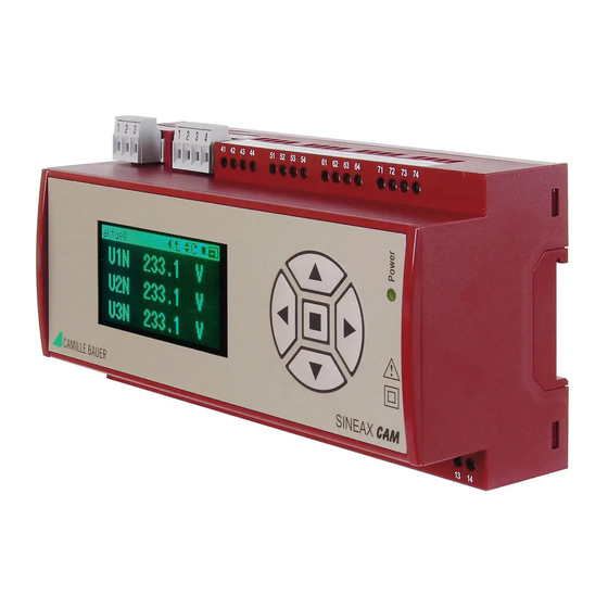
I/O-Module (optional, Terminals 41-74)
Up to 4 different groups of terminals (41-44, 51-54, 61-64,
71-74) with defi ned input/output functions are available
depending on the selected options. These groups are gal-
vanically isolated from each other and from the rest of the
device.
The following modules are available:
Analog outputs
2 active current outputs per group of terminals
Linearization:
linear, quadratic, kinked
Range:
0/4-20 mA (24 mA max.), unipolar
or
± 20 mA (24 mA max.), bipolar
Accuracy:
± 0.1% of 20 mA
Burden:
≤ 500 Ω (max. 10 V / 20 mA)
Galvanical isolation:
From all other connections (con-
nected within group of terminals)
Analog inputs
2 current inputs per group of terminals
Range:
0/4–20 mA (24 mA max.), unipolar
Accuracy:
± 0.1% of 20 mA
Galvanical isolation:
From all other connections (con-
nected within group of terminals)
Digital inputs/outputs
3 per group of terminals, in relation to software confi gurable as
passive inputs or outputs (all the same), acc. EN 61 131-2
Inputs (acc. EN 61 131-2 DC 24 V Type 3):
Function:
State input, pulse counter
Rated voltage:
12/24 V DC (30 V max.)
Input current:
< 7.0 mA
Counting
frequency (S0):
≤ 50 Hz
Logical ZERO:
– 3 till + 5 V
Logical ONE:
8 till 30 V
Switching limit:
approx. 6.5 V /2.6 mA
Outputs (partly acc. EN 61 131-2):
Function:
State output, pulse output,
self-monitoring
Rated voltage:
12/24 V DC (30 V max.)
Rated current:
50 mA (60 mA max.)
Switching
frequency (S0):
≤ 20 Hz
Load capacity:
400 Ω ... 1 MΩ
Digital inputs 125 V DC
3 per group of terminals
Function
State input
Rated voltage
48 / 125 V DC (157 V max.)
10
30 V DC, 2 A, 60 W
Input current
< 2.5 mA
Counting frequency (S0) ≤ 50 Hz
Logical ZERO
– 6 till + 20 V
Logical ONE
30 till 157 V
Switching limit
Approx. 25 V / 0.8 mA
HV-Input 110/230 V AC (for terminals 71, 74 only)
1 input for RTC synchronization or state recognition
Function:
Synchronization RTC, Logic
Rated voltage:
110 till 230 V AC (≥ 100 V AC,
≤ 264 V AC)
Frequency range:
45 till 65 Hz
Logical ZERO:
0 till 40 V AC
Logical ONE:
80 till 264 V AC
Switching limit:
Approx. 60 V AC / 1.9 mA ± 20%
7.3 Interface
Modbus connection (plug-in screw terminals 1, 2, 3)
Function:
Confi guration, Measurement acqui-
sition
Protocol:
Modbus RTU
Physics:
RS-485, max. distance
1200 m (4000 ft)
Baudrate:
Confi gurable
(1.2 till 115.2 kBaud)
Number of bus stations: ≤ 32
USB connection (USB Mini-B, 5 contacts)
Function:
Confi guration, Measurement acqui-
sition
Protocol:
USB 2.0
Subbus connection (plug-in screw terminals 1, 2, 3, 4)
Function:
reserved for future device options
Ethernet (RJ-45), optional
Function:
Confi guration, measurement acqui-
sition
Protocol:
Modbus/TCP or IEC 61850 (depen-
ding on the version ordered)
7.4 Further information
Power supply (Terminals 13, 14)
Option 1:
AC, 50 - 400 Hz:
100 ... 230 V ± 15%
DC:
100 ... 230 V ± 15%
Consumption:
≤ 10 W resp. ≤ 20 VA
Inrush current:
< 25 A / 0.3 ms
Option 2:
DC:
24 ... 60 V ± 15%
Consumption:
≤ 10 W
Limit module (Software function GW1 till 64)
64 Limit values for monitoring measurement limits
Limit for ON state:
programmable
Limit for OFF state:
programmable
Logic module (Software function LS1 till 32)
32 Logic functions to combine logical states: Limit values,
digital inputs, LS-states and default values. Output to digital
outputs, relays or other LS functions possible.
