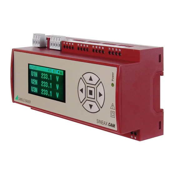
Camille Bauer SINEAX CAM Manual de Instruções - Página 10
Procurar online ou descarregar pdf Manual de Instruções para Instrumentos de medição Camille Bauer SINEAX CAM. Camille Bauer SINEAX CAM 12 páginas. Graphic display for sineax cam
Também para Camille Bauer SINEAX CAM: Manual de Instruções (19 páginas)

7.2 I/O-Interface
Relay (Terminals 21-23, 31-33)
Number:
2
Contacts:
Changeover contact
Load capacity:
250 V AC, 2 A, 500 VA
I/O-Module (optional, Terminals 41-74)
Up to 4 different groups of terminals (41-44, 51-54, 61-64,
71-74) with defi ned input/output functions are available
depending on the selected options. These groups are gal-
vanically isolated from each other and from the rest of the
device.
The following modules are available:
Analog outputs
2 active current outputs per group of terminals
Linearization:
linear, quadratic, kinked
Range:
0/4-20 mA (24 mA max.), unipolar
or
± 20 mA (24 mA max.), bipolar
Accuracy:
± 0.1% of 20 mA
Burden:
≤ 500 Ω (max. 10 V / 20 mA)
Galvanical isolation:
From all other connections (con-
nected within group of terminals)
Analog inputs
2 current inputs per group of terminals
Range:
0/4–20 mA (24 mA max.), unipolar
Accuracy:
± 0.1% of 20 mA
Galvanical isolation:
From all other connections (con-
nected within group of terminals)
Digital inputs/outputs
3 per group of terminals, in relation to software confi gurable as
passive inputs or outputs (all the same), acc. EN 61 131-2
Inputs (acc. EN 61 131-2 DC 24 V Type 3):
Function:
State input, pulse counter
Rated voltage:
12/24 V DC (30 V max.)
Input current:
< 7.0 mA
Counting
frequency (S0):
≤ 50 Hz
Logical ZERO:
– 3 till + 5 V
Logical ONE:
8 till 30 V
Switching limit:
approx. 6.5 V /2.6 mA
Outputs (partly acc. EN 61 131-2):
Function:
State output, pulse output,
self-monitoring
Rated voltage:
12/24 V DC (30 V max.)
Rated current:
50 mA (60 mA max.)
Switching
frequency (S0):
≤ 20 Hz
Load capacity:
400 Ω ... 1 MΩ
Digital inputs 125 V DC
3 per group of terminals
Function
State input
Rated voltage
48 / 125 V DC (157 V max.)
10
30 V DC, 2 A, 60 W
Input current
< 2.5 mA
Counting frequency (S0) ≤ 50 Hz
Logical ZERO
– 6 till + 20 V
Logical ONE
30 till 157 V
Switching limit
Approx. 25 V / 0.8 mA
HV-Input 110/230 V AC (for terminals 71, 74 only)
1 input for RTC synchronization or state recognition
Function:
Synchronization RTC, Logic
Rated voltage:
110 till 230 V AC (≥ 100 V AC,
≤ 264 V AC)
Frequency range:
45 till 65 Hz
Logical ZERO:
0 till 40 V AC
Logical ONE:
80 till 264 V AC
Switching limit:
Approx. 60 V AC / 1.9 mA ± 20%
7.3 Interface
Modbus connection (plug-in screw terminals 1, 2, 3)
Function:
Confi guration, Measurement acqui-
sition
Protocol:
Modbus RTU
Physics:
RS-485, max. distance
1200 m (4000 ft)
Baudrate:
Confi gurable
(1.2 till 115.2 kBaud)
Number of bus stations: ≤ 32
USB connection (USB Mini-B, 5 contacts)
Function:
Confi guration, Measurement acqui-
sition
Protocol:
USB 2.0
Subbus connection (plug-in screw terminals 1, 2, 3, 4)
Function:
reserved for future device options
Ethernet (RJ-45), optional
Function:
Confi guration, measurement acqui-
sition
Protocol:
Modbus/TCP or IEC 61850 (depen-
ding on the version ordered)
7.4 Further information
Power supply (Terminals 13, 14)
Option 1:
AC, 50 - 400 Hz:
100 ... 230 V ± 15%
DC:
100 ... 230 V ± 15%
Consumption:
≤ 10 W resp. ≤ 20 VA
Inrush current:
< 25 A / 0.3 ms
Option 2:
DC:
24 ... 60 V ± 15%
Consumption:
≤ 10 W
Limit module (Software function GW1 till 64)
64 Limit values for monitoring measurement limits
Limit for ON state:
programmable
Limit for OFF state:
programmable
Logic module (Software function LS1 till 32)
32 Logic functions to combine logical states: Limit values,
digital inputs, LS-states and default values. Output to digital
outputs, relays or other LS functions possible.
