Egardia Extender Installatiehandleiding - Pagina 2
Blader online of download pdf Installatiehandleiding voor {categorie_naam} Egardia Extender. Egardia Extender 5 pagina's. Egardia extender installation guide

Website Egardia
www.egardia.com
You may register up to 70
accessories with the extender.
The smart plug and the Egardia
camera cannot be registered.
When the maximum amount of
accessories have been
registered the extender emits 6
short beeps.
INSTALLATION GUIDE EXTENDER
Congratulations on the purchase of your Egardia extender.
Customer service
Please visit www.egardia.com if you would like further information about the installation and use of
Egardia. The answers to a number of frequently asked questions can be found at
www.egardia.com/userquestions.
This package has been put together with care. Please contact our customer service if you would like
any help during installation or if something is missing from the package. Never return a package
without prior instruction from our customer service.
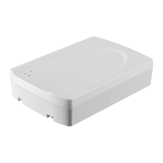
Extender
The extender extends the range between the Egardia accessories and the Egardia gateway.
Without obstacles the maximum range between the Egardia accessories and the Egardia gateway
is 30 meter. The extender will extend the range between the Egardia accessories and the Egardia
gateway to approximately 60 meter (see fig.). The effective range within the property is dependent
on obstacles that could cause interference of the signal, such as metal objects and strong
electromagnetic sources.
Power supply and internal battery
The extender must be connected with the supplied power adapter to the 230V power grid. In the
event of a power failure the extender will continue to function on its emergency power supply for
approximately 24 hours. You can add up to two extenders to 1 gateway.
OVERVIEW EXTENDER
Indicator light Status (red) – The red indicator light glows to indicate a change of status.
1.
Indicator light Activity (green) – The green indicator light glows to indicate an activity.
2.
Indicator light Fault (yellow) – The yellow indicator light glows to indicate a malfunction.
3.
Power port – To connect the extender to the power supply (230V) using the supplied power
4.
adapter.
Battery switch – To turn the extender on or off.
5.
DIP switch – To adjust the settings of the extender.
6.
Reset button – To restart the extender.
7.
Erase button – In combination with DIP switch 3 all registered accessories and the gateway
8.
are erased from memory.
Mounting holes – To secure the extender to the mounting bracket.
9.
10. Speaker – Emits the confirmation sounds.
Erasing memory
To erase the extender's memory, set DIP switch 3 to "ON". Hold the erase button for at least 10
seconds. The extender emits a beep. All registered accessories and the gateway are now erased
from the memory of the extender. Set DIP switch 3 back to "OFF".
1
