Atkinson Electronics GSCM Podręcznik - Strona 5
Przeglądaj online lub pobierz pdf Podręcznik dla Jednostka sterująca Atkinson Electronics GSCM. Atkinson Electronics GSCM 16 stron. Generator start control module
Również dla Atkinson Electronics GSCM: Instrukcja obsługi i instalacji (16 strony)

4
GSCM Starting Sequence
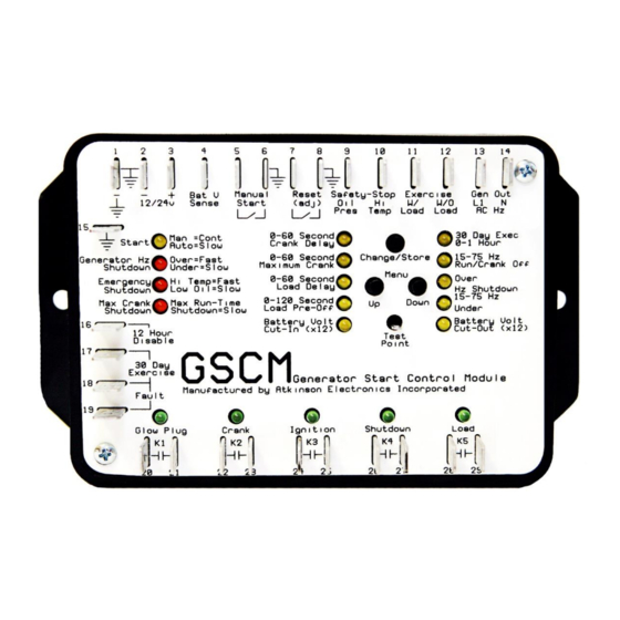
The GSCM indicates that it is ready to receive a start signal by blinking the start LED once every 5 seconds. The GSCM is started by
shorting terminal 5 to ground (terminal 6) for manual start mode. The module may also start in automatic mode based on a battery
voltage, See AUTOMATIC STARTING FOR BATTERY CHARGING section, or a 30 day exercise cycle. The start LED is lit continuously to
indicate that a manual start signal has been applied. The various adjustment LEDs blink during their respective generator controller
time delay periods. If the GSCM detects an AC frequency input greater than zero (the generator is already running) it will not execute
a start sequence, but will light the Hz LED continuously. The generator starting sequence is as follows:
1. The start LED blinks once every 5 seconds to indicate that the GSCM is in ready mode. When a manual start signal is
received, the start LED lights constantly. After a 5 second delay, K4 (shutdown) relay closes to ensure the generator is not
running before beginning the cranking sequence. After 7 seconds the K1 (glow plug) relay closes to energize the glow
plug(s). The K1 relay remains closed until either the generator starts or the max crank time is reached.
2. An adjustable 5 to 60 second crank delay period starts when the K1 (glow plug) relay is energized.
3. After the crank delay period, K2 (crank) relay closes to cranks the starter, and K3 (ignition) relay closes to energize the
ignition. The K2 relay remains closed until either the generator starts or the maximum cranking time period (0 to 60
seconds) is reached.
4. If the generator fails to start after cranking, K1, K2 and K3 relays open for a resting period equal to twice the maximum
cranking time adjustment, the maximum crank LED blinks during this period. Halfway through the resting period K4
(shutdown) relay energizes for 7 seconds to ensure the generator did not start before beginning the cranking sequence
routine again. If the generator starts and shuts down after each starting attempt , operator needs to check the AC
feedback signal to make sure it is present when the generator starts and is running.
5. If the generator fails to start after 4 cranking attempts, K1, K2 and K3 relays open, K4 (shutdown) relay closes for 5
seconds and then opens to ensure the generator is not running, then the maximum crank shutdown LED lights and the
GSCM enters the maximum crank lockout condition. This lockout condition remains until the GSCM is reset by
momentarily shorting the reset terminals 7 and 8 together, after which the start LED blinks for 60 seconds and then enters
ready mode. Powering down the GSCM for 5 seconds and powering it back up will also clear the maximum crank lockout
condition, with the GSCM returning to ready mode.
6. When the generator starts, K2 (crank) relay immediately opens, stopping the cranking, K1 (glow plug) relay remains
energized for an additional 5 seconds and then opens, de-energizing the glow plugs or removing a low oil pressure lockout
during the starting routine. The K3 (ignition) relay remains closed during the run operation. A valid run condition is
determined by the generator's AC output frequency exceeding the 30Hz run/crank disconnect setting (adjustable
between 15 and 75Hz).
7. If the generator starts but shuts down after a few seconds due to a fuel problem, etc., the start sequence will revert to
ready mode after a 60 second delay period in which the start LED blinks rapidly. The GSCM will then try to start the
generator again in manual mode or after a 5 minute delay period in auto-stat mode. When the run condition is detected,
the GSCM enters a load transfer delay period, before energizing the K5 (load) relay, the load delay LED blinks during the
delay.
8. After the load transfer delay period, K5 (load) relay energizes to transfer the electrical load to the generator.
9. The generator continues to run until one of the following occurs: the manual start signal is no longer received, the auto
battery charge voltage is reached, the 30 day exercise cycle time out or either an oil pressure or high temperature fault
condition occurs.
10. During normal shutdown, K5 (load) relay opens and the GSCM enters the pre-off (cool down) time period, indicated by
the load pre-off LED blinking.
11. When the pre-off period expires, K3 (ignition) relay opens, ½ second later the K4 (shutdown) closes, to shut down the
generator by grounding the ignition, etc. It remains closed for 5 seconds after the AC Hz signal from the generator goes to
zero, ensuring the generator has shutdown.
12. If the manual start signal is removed or switch is turned off before K5 (load) relay energizes, K3 (ignition) relay opens, then
K4 (shutdown) relay energized shutting down the generator. The GSCM then enters a 60 second delay period before
returning to ready mode.
13. If the load pre-off time delay is set to 0V, then the K5 (load) and K3 (ignition) relays de-energize simultaneously for
shutdown followed by K4 (shutdown) relay energizing to ensure the generator shuts down.
14. The generator remains off until another start signal is received.
www.atkinsonelectronics.com
800.261.3602
5
Circuit Board Division
Revised 09/18
