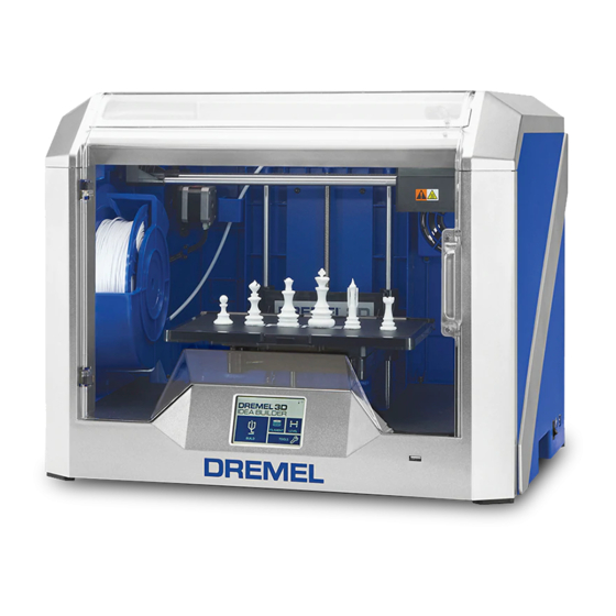
Dremel 3D40 Idea Builder Instrukcje - Strona 3
Przeglądaj online lub pobierz pdf Instrukcje dla Drukarki 3D Dremel 3D40 Idea Builder. Dremel 3D40 Idea Builder 5 stron. Clogged heatsink tube replacement
Również dla Dremel 3D40 Idea Builder: Skrócona instrukcja obsługi (2 strony), Podręcznik (4 strony), Instrukcje serwisowe (2 strony)

Step 4: Remove the Leveling Servo Assembly
1. Remove the three screws holding the servo motor bracket
in place with a T10 Torx (star) bit.
Figure 8: Unscrew servo motor levelling switch chassis
2. Get a visual understanding of how the levelling arm is
located and oriented in the assembly (see picture below)
and then pull the servo motor assembly vertically upwards
away from the extruder.
Figure 9: Take note of how levelling switch is located
and oriented before chassis removal.
Step 5: Disconnect the Extruder Circuit Board
1. Disconnect the leveling switch (black and red wires) and
servo motor (red, brown, and yellow) from the extruder
circuit board. When removing these, always remove by the
plastic connectors. Never pull by the wires - this can
damage or break the connectors.
Figure 10: Disconnect encircled connectors
Step 6: Reassemble the Extruder
1. Replace the leveling servo assembly carefully by maneu-
vering the levelling arm through the extruder chassis.
2. Replace the three screws holding the servo motor chassis
in place as shown in Figure 8.
3. Reconnect both wire connectors to the extruder circuit
board as shown in Figure 10.
4. Loop the shielded circuit cable through the plastic guide
bracket. Refer Figure 7.
5. Press the black connector pins on the shielded ribbon
cables and align with the receptacle as shown in Figure 6.
Gently push the ribbon cable onto the receptacle and
release the black pins. An audible "click" should be heard
when it is reconnected.
6. Reconnect the filament runout switch from the extruder top
cover to the circuit board. Refer Figure 5.
7. Replace the top cover and the two screws attaching it to
the extruder. Refer Figure 4. PLEASE NOTE: After replac-
ing the top cover ensure that no wires are exposed out of
the extruder body. If any wires are exposed or hanging out,
the extruder top cover will need to be removed and re-
placed.
Step 7: Calibration
This step will outline how to calibrate the leveling arm and
the z-offset for the extruder. The new leveling arm does not
know where it is in rotation before calibration, so the following
instructions will calibrate it to the correct position.
1. With the printer turned off, insert the supplied USB stick
into the USB port on the front of your 3D40.
2. Turn on the printer and wait for the calibration screen to
appear.
3. The "level arm set: (1/2)" will show up on the screen. The
Up and Down orientations have + and - adjustment
buttons. The adjusted angle can be seen in the black box
between the + and – buttons.
a. Press "test" once to move the levelling arm down.
Figure 11: Levelling Arm visible after pressing "test"
3
