Dresser Masoneilan SVI II AP Skrócona instrukcja obsługi - Strona 15
Przeglądaj online lub pobierz pdf Skrócona instrukcja obsługi dla Sprzęt nagrywający Dresser Masoneilan SVI II AP. Dresser Masoneilan SVI II AP 20 stron. Smart valve interface with remote position sensor
M M a a s s o o n n e e i i l l a a n n D D r r e e s s s s e e r r
Single Acting Positioner
Single Acting Positioner
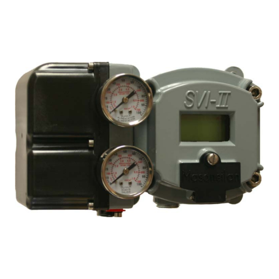
F F i i gu
gure re 4 4
Air r P P or
Ai
The supply and output connections for
The supply and
output connections for the SVI II AP
of the pneumatic block, are tapped 1 ⁄ ⁄ 4 inch NPT
of the pneumatic block, are tapped 1
front, supply is toward the back.
front, supply is
toward the back. T T wo pressure gauges, output
supply on bottom, are located on the front of the pneumatic block.
supply on bottom, are located on the front of
Maximum allowable air supply pressure to the SVI II AP varies
Maximum allowable air supply pressure to the SVI II AP varies
according to actuator, valve size,
according to actuator
tables in valve specification sheets to determine the correct positioner
tables in valve specification sheets to determine the correct positioner
supply pressure. Minimum supply pressure should
supply pressure.
Minimum supply pressure should be 5 to 10 psi above
maximum spring pressure but may not exceed the rated actuator
maximum spring pressure but may not exceed
pressure.
pressure.
Supply
Supply
orts ts o o n n Si Sin n g g le le Ac
Acti tin n g g P P os
the SVI II AP, located on
4 inch NPT. . Output is toward the
wo pressure gauges, output on top,
, valve size, and valve type.
and valve type. See Pressure Drop
Output
Output
osi i ti tion
oner
er
8 8
S S V V I I I I I I A A P P Q Q u u i i c c k k S S t t a a r r t t G G u u i i d d e e
, located on bottom
bottom
Output is toward the
on top,
the pneumatic block.
See Pressure Drop
be 5 to 10 psi above
the rated actuator