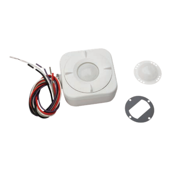
Daintree GE current WHS100 Instrukcja instalacji
Przeglądaj online lub pobierz pdf Instrukcja instalacji dla Akcesoria Daintree GE current WHS100. Daintree GE current WHS100 9 stron. Wireless high bay sensor

Daintree
™
High Bay Sensor
(WHS100)
BEFORE YOU BEGIN
Read these instructions completely and carefully.
Save these instructions for future use.
WARNING
Risk of electrical shock. Disconnect power before servicing or
installing product.
Install in accordance with National Electric Code and local codes.
• Keep the sensor lens clean.
• Avoid touching the PIR sensor element.
• After powering the sensor, allow up to three minutes
for initialization.
The WHS100 Wireless High Bay Sensor is a line powered
control component within the Daintree Networked wireless
building controls platform. It enables wireless control of individual
luminaires and has an integrated motion sensor. It comes with
interchangeable sensor lenses to provide occupancy based
control for high, medium, and low mount lighting applications.
The WHS100 provides ON/OFF and 0-10V dimming control of
ballasts and LED drivers. Its wet location rating and mounting
through a standard ½" knockout, allows installation on a variety
of indoor and outdoor fixture types.* Model WHS100 mounts to
the side of a fixture; WHS100-BM (Base Mount) mounts to the
bottom of a fixture.
The WHS100 contains a standard ZigBee radio that operates
seamlessly with other standard ZigBee wireless products in
the Daintree Networked. The WHS100 serves as a ZigBee
mesh network router, includes the capability to monitor and
measure the energy consumption of the lighting load being
controlled, and enables automatic fault detection.
1
Installation Process
1. Determine the mounting location. See Mounting.
2. Record the sensor's IEEE address and location on the
facility floor plan. Make sure the IEEE number will be visible
after the sensor is mounted. See IEEE Address Labels.
3. Remove the tightening ring from the threaded nipple.
4. Insert the sensor wires and threaded nipple through the
knockout on the fixture.
Wireless
CAUTION
Risk of injury. Wear safety glasses and gloves during installation and
servicing.
5. Thread the sensor wires through the tightening ring and screw
the ring onto the nipple on the inside of the fixture to secure
the sensor to the fixture wall.
6. Wire the sensor to the line voltage supply and 0-10V dimming
input to the driver or ballast. See Wiring.
7. Apply power to the fixture. After initialization, the Green LED
flashes each time occupancy is detected.
8. Reset the WHS100: press and hold the Utility button for 5
seconds. Release the button when both the red LED and the
green LED begin to flash rapidly.
The red Network LED flickers while the WHS100 attempts to join a
ZigBee network. If it is unable to join, it automatically retries every
20 seconds until it succeeds. When successful, the red LED either
flashes slowly, or if the WHS100 is already assigned to a zone, the
red LED is off. See LED Operation.
Note, the sensor will not be able to join a network until a
Wireless Area Controller (WAC) is commissioned and a WAC in
range is commanded (through CSM) to "discover devices."
See Joining the ZigBee Network.
9. Initiate the Installation Test Mode: Momentarily press the blue
Utility button under the lens. Both LEDs flash simultaneously,
with one short blip of the green LED between flashes.
For dimming lights, the light is raised to the maximum level
over a 3-second period then turns off, and then repeats.
For on/off lights, the light turns ON then OFF and repeats.
When operation is confirmed, exit Installation Test Mode:
momentarily press the Utility button again, or wait 5 minutes
for the mode to time out.
Installation Guide
WHS100 | DT109
