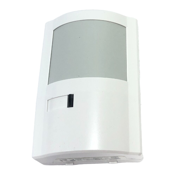
DSC AMB-300 Instrukcje instalacji - Strona 3
Przeglądaj online lub pobierz pdf Instrukcje instalacji dla Czujniki bezpieczeństwa DSC AMB-300. DSC AMB-300 4 stron. Addressable pir detector

Mounting
To open the case, use a small flat blade screwdriver and gently push in the tab at the
bottom of the case and pull the cover straight out at the bottom. Loosen the printed
circuit board screw, and push the board up as far as it will go. Using a small screw-
driver, remove the appropriate knockouts for the mounting screws. Remove the
desired wiring entrance knockouts located at the top or bottom of the backplate.
Mount the backplate.
Locate mounting screws diagonally opposite each other to prevent the case from
warping.
Device Enrollment
The serial number located on the back of the device must be enrolled into the alarm
control panel via Installer's Programming ([✱] [8] [Installer's Code]). This procedure is
outlined for the PC4010/4020 in the control panel Installation Manual and for the
Power panels in the PC5100 Installation Manual.
WARNING: Connect only DSC Addressable Series devices to the addressable
loop connections. Connection of ANY other type of device will impair operation.
Any devices other than Addressable Series devices which require power to oper-
ate must be powered separately.
Vertical Adjustment
NOTE: Range and dead zones may vary due to settings.
Using the figures listed below, set the vertical adjustment to get the desired coverage.
Ensure that the PCB retaining screw is tightened just enough to prevent board movement.
Moving the circuit board down will increase the far range and bring the near beams closer
to the mounting wall. Moving the circuit board UP will reduce the far range and move the
near beams farther out from the mounting wall. Moving the circuit board UP too much will
cause the far beams to "look" above the target; as a result, the range may appear shorter.
Jumper J1 selects between harsh and normal environments. For a typical environ-
ment or one containing a small pet (height less than 1.2 ft/0.36 m), set the unit as nor-
mal (J1 ON). For a large pet and multiple pets, the jumper J1 should be removed.
Walk Testing
Once the detector has been set up, walk test the entire area where coverage is
desired. Should the coverage be incomplete, readjust or relocate the detector to
obtain full coverage.
IMPORTANT NOTE: Upon installation, the unit should be thoroughly tested to
verify proper operation. The end user should be instructed on how to perform
walk tests, and should walk test the detector weekly.
