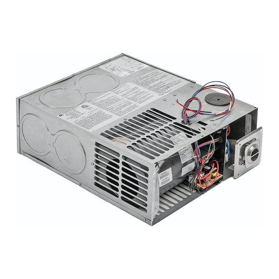
Atwood AFMD25 Techniczna instrukcja instalacji - Strona 3
Przeglądaj online lub pobierz pdf Techniczna instrukcja instalacji dla Piec Atwood AFMD25. Atwood AFMD25 19 stron. Afm series hydro flame

Spacing of 1/4" to ducting within 3 feet of furnace must be provided
unless UL listed wire bound vinyl ducts are used. All ducting
material used to be rated for continuous use at minimum of 200°F.
Clearances are specifically for plywood or similar building materials
surrounding the furnace (i.e. Furnace should not be located under
furniture or in a closet space where clothing or other material could
be located).
To install without adding the 36 sq. in. cutout on the blower side
supply the unit (blower side) with 2" clearance full length of the unit.
Furnace efficiency rating is a thermal rating determined under
continuous operating conditions, independent of any installation.
Efficiency rate is given at 76% minimum; actual efficiency rating
may be higher.
Return air is supplied through openings in furnace casing. All return
air passages must be kept clear for furnace to function properly.
Refer to Minimum clearance to floorboards, walls & similar
combustible building material.
The total unobstructed return air opening size(s) must not be less
than specified in Table 1. Failure to meet minimum return air
requirements nullifies furnace warranty.
INSTALLATION AND SAFETY CODES
USA and Canada – follow all applicable state and local codes – in the
absence of local codes or regulations, refer to current standards of:
Recreation Vehicles ANSI A119.2/NFPA 501C
National Fuel Gas Code ANSI Z223.1 and/or CAN/CGA B149
Installation Codes
This furnace must be installed in accordance with the
manufacturer's instructions and the manufactured Home
Construction and Safety Standard, Title 24 CFR, part 3280, or when
such standard is not applicable, the Standard for Manufactured
Home Installations. (Manufactured Home Sites, Communities and
Set-Ups), ANSI A255.1 and/or CAN/CSA-Z240 MH Series M92
Canadian Standard for Mobile Homes."
ANSI A 255.1 and/or CAN/CSA-Z240.6.2 MH Series, Mobile Homes
Ground National Electrical Code ANSI/NFPA 70 and/or CSA C22.1,
Part 1
Park Trailers ANSI 119.5
GENERAL FURNACE LOCATION AND INSTALLATIONS
All models can be installed in either a horizontal or vertical mounting
position horizontal installed units have the gas line positioned on top
or rear, vertical installed units have the vent located at floor level
and gas line at right side and rear.
Always install furnace through an exterior wall.
DO NOT install furnace near tilt-out rooms, slide-outs, doors or
other projection that could obstruct furnace exhaust.
Locate furnace near midpoint of coach for single furnace
applications.
Installation must provide accessibility if any repairs are necessary to
the furnace. Failure to meet this requirement will create additional
labor costs that will be the responsibility of the installer.
DO NOT install vent in areas where projection or door openings
come within 6" of vent opening.
DO NOT install furnace in an area where wires, pipes or other
objects will interfere with installation or operation of furnace.
DO NOT install furnace on material that restricts return air, such as
directly on carpet, or soft material (like vinyl). If you must install
furnace on carpet or soft material, install furnace on cleats, or on a
wood or metal panel extending the full width and depth of furnace
plus minimum clearance to combustibles.
DO NOT use petroleum or citrus type cleaner on plastic parts, as
damage may occur.
CAUTION: Due to the differences in vinyl siding materials this
appliance should not be installed without first consulting with the
manufacturer of siding.
A gas-fired furnace for installation in a residential garage must be
installed so the burner(s) and the ignition source are located not
less than 18 in (457mm) above the floor and the furnace must be
located or protected to avoid physical damage by vehicles.
FURNACE INSTALLATION
The furnace should always be installed level (front to back, side to
side) to prevent water intrusion into the interior.
Set aside venting and outer door parts for installing on the outside
of coach.
NOTE to assure sufficient return air to circulating blower maintain
specified clearances see table 4.
If units are installed using the small outside vent system access to
the inside of the coach must be provided directly in front of the unit
to remove for service suggested opening size 17" wide by 8-3/8"
height.
Remove knockouts from furnace and install duct adapters for side
discharge by inserting back flange over casing and inserting tab into
square notch, then twist adapter 90°.
Insert furnace into cabinet opening and secure with two screws
through casing legs to floor. Units are secured by means of door or
vent systems through the coach sidewall with casing legs at the
rear.
Attach flexible ducting over duct adapters and secure. All flex
ducting requires rating of 200°F.
Run ducting to locations keeping bends and excess ducting to a
minimum and secure to registers.
Connect wiring to located on the top of the furnace. See wiring
connection section.
Connect gas line to top or rear of furnace. See gas connection
section.
1.
Cut the required exterior wall opening for your venting system see
Figure 1.
2.
Configure furnace for ducting option to be used refer to duct
configurations table 2.
3.
Install furnace into opening and attach ducting to adapters.
4.
Make gas and electrical connections, which are located on the top
of the unit.
5.
See door or vent installation instruction below on how to complete
the venting system.
SIDEWALL CUTOUT
* Recommended exterior wall thickness 0" to 2-1/2".
* Small vent system 0" to 2-1/4".
WALL CUTOUTS Table
Side Wall Cutout Small Vent Max
Wall Thickness 2-1/2"
Side Wall Cutout Standard Door
(horizontal or vertical)
Side Wall Cutout Flush Door
(corner cut requires 3/4" radius)
(horizontal or vertical)
DO NOT oversize hole – over sizing can result in water leakage.
Zero clearance around air intake cutout for best sealing condition.
3
A
B
-
-
3-1/4" Dia.
7-1/2"
17" MAX
MAX
18-3/4"
9-3/8"
MAX
MAX
Figure 1
D
