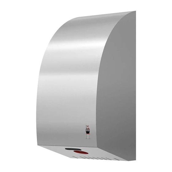
DAN DRYER 288 Podręcznik użytkownika - Strona 3
Przeglądaj online lub pobierz pdf Podręcznik użytkownika dla Suszarka DAN DRYER 288. DAN DRYER 288 6 stron. Stainless design turbo hand dryer

GENERAL SAFETY INFORMATION
!
WARNING
• All units must be equipped with a 3-wire service. Connect the ground wire according to the
instructions.
• This product must be installed only by qualified persons. Use 2.0 mm2 (AWG) NO.14 wiring.
• Turn off the power to the unit before servicing or cleaning. All wires must be disconnected.
• Incorrect installation, defect power cords, or failure to properly ground unit could result in
electrical shock or life-threatening injuries
NOTE
We do not recommend to install this product less than 300 mm above washbasin, tabletop or
other surface. This product is suitable for indoor use only.
Type Y connection: If the power supply cord is damaged, it must be replaced immediately.
Only qualified persons shall be permitted to replace the cord to avoid a hazard. Disconnect the
electricity supply cord according to instructions.
This product is not intended for use by persons (inclusive children) with reduced physical,
sensory or mental capabilities, or lack of experience and knowledge, unless they are
supervised or have been given instruction concerning use of the product by a person
responsible for their safety.
Children should be supervised to ensure this product is used correctly.
CIRCUIT DIAGRAM
4
INSTALLATION
• Make sure the main breaker is turned off. Installation must be carried out by
a qualified person in accordance with standards applicable in the country where the
equipment is to be installed.
• Place template against the wall at desired height (see mounting height
recommendations).
1. Dismount the casing by removing the 2
securing screws.
3. Attach the base plate of the hand
dryer to the wall with the screws
supplied with the unit
5. Connect supply wires to terminal block:
N
L
2. Place the template
on the wall
at the desired location
(see recommended
installation height).
Drill (4) holes as
indicated.
4. Insert the power cord through the inlet hole.
Fasten with the retaining clip
CONNECTION:
A.
Connect Live wire (red or brown) to the terminal
block marked "L"
B.
Connect Neutral wire (blue) to the terminal block
marked "N"
C.
Connect Ground wire (green and yellow) to terminal
block marked " "
NOTE
Colours of live and neutral wires depend on the
supply voltage.
5
