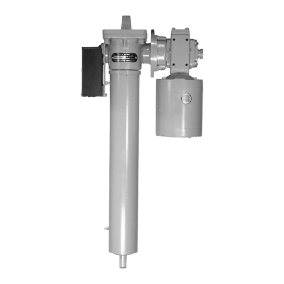
Duff-Norton SuperCylinder Series Instrukcja instalacji, obsługi i konserwacji - Strona 5
Przeglądaj online lub pobierz pdf Instrukcja instalacji, obsługi i konserwacji dla Kontroler Duff-Norton SuperCylinder Series. Duff-Norton SuperCylinder Series 12 stron. Linear actuators

WARNING
Do not touch any internal parts of limit
switch unless power has been
disconnected.
2. Remove limit switch cover.
With the clevises connected, jog actuator to its re-
tracted position, making sure that the rod is
extended at least 1/2" from the jam closed position.
Observe white plastic limit switch nuts and be sure
that neither one travels into a switch. If contact is
imminent, disconnect power and screw nut away
from switch, as described in the next paragraph.
3. Refer to Figure 1 for limit switch nut identification.
Remove the screw "A" and nut guide "B". Rotate
3-1. Lubrication
Shell Oil Co. Albida LC Ep #2 (Shell Product Code 70311)
has been thoroughly evaluated in Duff-Norton actuators
and has demonstrated superior lubricating properties af-
fecting both wear life and maximum duty cycle.
Duff-Norton is not aware of an equivalent grease. If this
grease is not available in your area, please contact your
local supplier for their recommendations. Greases con-
taining molybdenum disulfide should never be used.
For severe service conditions, the actuators should be
lubricated more frequently using the above grease (daily
to weekly depending upon the conditions). If duty is heavy,
an automatic lubrication system is strongly recommended.
1. Lubrication Points - The SuperCylinder has two
grease fittings, one in the worm housing and one at
the tube guide bushing. Shell Albida LC Ep #2 is
recommended for both.
2. Frequency - The lubrication schedule will vary de-
pending on the severity of use. Lubrication every
50 hours of actual operation is suggested as a guide-
line.
3. Quantity - During operation, there will be migration
of grease from the worm gear housing into the tube
area. There will also be grease migration from the
outer tube guide bushing into the tube, and possi-
bly some loss through the tube wiper seal. The
actual quantity of grease needed to replace this
grease cannot readily be determined. Using a stan-
dard hand-pumped grease gun, a rough rule of
thumb is to inject into each grease fitting one pump
of grease for every 1000 pounds of actuator capac-
ity
4. Grease Loss - Over time, spent grease will accu-
mulate inside the tube. A considerable volume of
the "retract" nut toward the switch until the switch
just clicks. Rotate nut 1/2 turn (5 slots) farther (to
allow for drift), and install nut guide.
4. Restore power and jog the rod out for a few sec-
onds, then retract it until it is cut off by the limit switch.
If fine adjustment is needed, disconnect power,
move nut one or two slots at a time and recheck.
The amount of drift can vary widely on Acme screw
models without brakes. On these models, drift will,
in general, be greater under light loads. When set-
ting limit switches, it is best to operate Acme screw
models at lightest expected load, and to operate
ball screw models at greatest expected load.
5. Jog actuator to its extended position, repeating all
the steps from paragraphs 2-4 for the "extend" switch
and nut.
Section III
Lubrication
grease can exist there without noticeable effects.
Depending on the orientation of the actuator, it may
eventually begin to ooze grease from the tube vent
or from the wiper seal. This is not an indication of a
problem, but evidence of internal lubricant circula-
tion. If these grease emissions are objectionable,
the outer tube may be removed and surplus grease
cleaned out.
3-2. Motor Reducer Lubrication
Unless loss of oil is apparent, the reducer will not nor-
mally require relubrication. For most applications, Mobil
SHC636 synthetic gear oil is the recommended lubricant.
Reducers should be filled approximately half full of oil. A
pipe plug should be apparent at this level, which can be
used as a level plug.
For more detailed discussion of reducer lubrication re-
quirements, refer to the reducer instruction sheet.
3-3. Motor and Reducer Bearings
All standard motors for this product should have perma-
nently sealed and lubricated bearings that do not require
maintenance.
Larger models of motor reducer may have grease fittings
for bearing lubrication. If fittings are evident on the motor
reducer, they should receive one shot of grease at the
same time the actuator is relubricated.
3-4. Clevis Pins
Clevis pins are very subject to wear and can be a source
of creaking or popping noises. Removal, cleaning, inspec-
tion, and regreasing of clevis pins at each scheduled
lubrication is recommended.
5
