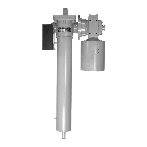
Duff-Norton SuperCylinder Series Instrukcja instalacji, obsługi i konserwacji - Strona 6
Przeglądaj online lub pobierz pdf Instrukcja instalacji, obsługi i konserwacji dla Kontroler Duff-Norton SuperCylinder Series. Duff-Norton SuperCylinder Series 12 stron. Linear actuators

Other than the lubrication described in the previous sec-
tion, regular maintenance should not be required. If
disassembly is required to repair damage or a failure, the
following procedure may be followed.
4-1. Disassembly (Refer to Figure 5-1)
1. Remove SuperCylinder from installation and move
to a work area. Watch for oil spillage from the re-
ducer vent plug.
2. Remove motor, reducer, and limit switch (if fitted).
Each of these can be withdrawn after removing its
four mounting screws.
3. Loosen two setscrews on outer tube. Unscrew tube
and pull off. Clean excess grease from screw and
tube.
4. Remove four screws from each worm flange and
remove flanges. Tap worm to one side.
5. Loosen two setscrews in flange of shell cap. Re-
move cap with screw and tube assembly.
6. Withdraw worm with bearings.
7. Unless there is a reason for removal, leave clevis
bolted to shell, as there is sealer between the two
parts.
4-2. Screw & Tube Disassembly
If problem is isolated to worm gear
area, do not disassemble tube from nut.
1. Spread and remove nylon nut guide from inner end
of translating tube.
2. Loosen two setscrews holding lifting nut. These are
installed with thread locking adhesive and may re-
quire heating.
3. Clamp lifting nut in vise. Insert bar in clevis hole
and unscrew translating tube.
4-3. Gear Removal
1. Depending on size, the nut holding on the worm
gear may be self-locking or may use a pin or a set-
screw for retention. Remove pin or loosen setscrew
if used.
2. Clean all grease from an area of the screw and
clamp that area in a vise with soft jaws. Remove
the gear nut. Use an impact wrench on hex nuts, if
available.
3. Pull gear from screw. There may be slight resis-
tance, but this should not be a hard pull.
4. Keep bearing races together and note which one
was in each location.
6
Maintenance
Note
Section IV
4-4. Screw and Nut Inspection
Clean excess grease from the screw and nut.
1.
Inspect the screw thread areas for any wear,
pitting, gouges, spalling, brinelling, or corrosion.
Any deterioration of the thread contact surfaces
is cause for replacement.
2. If screw is undamaged, clamp it in a vise with soft
jaws and check the nut for backlash. Push back
and forth on the nut, without rotation. Movement
should be no more than shown in Table 1. Use a
dial indicator if available.
3. It is not uncommon for nuts to exhibit wear before
any damage to the screw. If this is the case, a new
nut can be fitted without screw replacement.
4-5. Lifting Nut Removal
Removal of a ball nut from the screw is
not recommended unless there is a
reason to do so.
1. Clamp screw in vise with soft jaws and use an im-
pact wrench to loosen the stop washer bolt in the
end of the screw. This bolt is installed with high
strength locking adhesive. The use of heat is rec-
ommended.
2. Acme screw nuts can then be removed without pre-
caution. Ball screw nuts, if already determined to
need replacement, can be screwed off, with balls
being lost as it comes off the screw.
3. If ball nuts are to be reused, it is recommended that
an arbor be made for capturing balls. This will elimi-
nate the need to reload balls. The arbor can be
made from any stiff material and should be about
2" longer than the ball nut. A piece of tubular mate-
rial is easier to secure inside the nut, but a solid bar
can be used. Arbor diameters are given in Table 2.
Table 1
Max.
Screw O.D
Backlash
1.0"
.008"
1.17-2.50"
.025"
3.0"
.050"
Note
