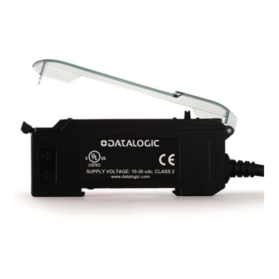
Datalogic S70 Podręcznik
Przeglądaj online lub pobierz pdf Podręcznik dla Akcesoria Datalogic S70. Datalogic S70 18 stron. Advanced sensor with dual digital displays for use with plastic and glass fiber optic assemblies
Również dla Datalogic S70: Skrócona instrukcja obsługi (10 strony)

For complete technical information about this product, including dimensions, accessories, and specifications, see www.datalogic.com.
WARNING: Not to be used for personnel protection
Never use this device as a sensing device for personnel protection.
Doing so could lead to serious injury or death. This device does not include the self-checking redundant
circuitry necessary to allow its use in personnel safety applications.
A sensor failure or malfunction can cause either an energized or de-energized sensor output condition.
S70-2-E1-N
S70-2-E1-P
S70-5-E1-N
S70-5-E1-P
S70-5-E1-PZ
S70-5-E2-N
S70-5-E2-P
CONNECTIONS
NPN Version
LOAD
Load
IO-Link Version
(C/Q)
Load
(Q)
Load
NOTE: Open lead wires must be connected to a terminal block.
1
A model with a QD connector requires a mating cordset.
S70 Series
Advanced sensor with dual digital displays
for use with plastic and glass fiber optic assemblies
Figure 1
Outputs
Single NPN
Single PNP
Single NPN
Single PNP
Dual outputs, 1 push-pull IO-Link and 1 PNP
(complementary outputs)
Single NPN
Single PNP
10-30 VDC
Remote
Programming (N.O.)
18-30 VDC
1
2
3
4
5
6
7
2 m cable, 4-wire
Integral M8 Pico QD connector, 4-pin
Integral M8 Pico QD connector, 4-pin
PNP Version
10-30 VDC
LOAD
Load
Remote
Programming (N.O.)
1
Output LED
LO/DO Switch
RUN/PRG/ADJ Mode Switch
Lever Action Fiber Clamp
Red Signal Level
Green Threshold
+/SET/- Navigation key
1
Connector
Key
1 = Brown
2 = White
3 = Blue
4 = Black
Pico
4
2
1
3
