4x4 Traction BeadLocker Instrukcja instalacji - Strona 2
Przeglądaj online lub pobierz pdf Instrukcja instalacji dla Akcesoria samochodowe 4x4 Traction BeadLocker. 4x4 Traction BeadLocker 8 stron. Internal beadlock

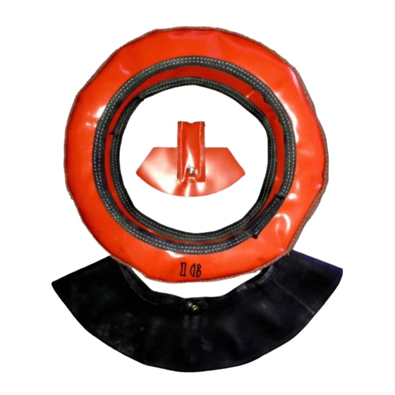
MOUNTING SUMMARY
The only modification required to install the 4x4
Traction BeadLocker™ Internal Beadlock, is to drill
one hole in your rim (wheel) for the beadlock inner
tube, which must be done correctly. 4x4 Traction
cannot be held responsible for damaged rims due to
drilling errors. The balance of the installation process
involves mounting and centering the inner tube
within the beadlock casing on the rim, seating the
beadlock beads, fitting the special air channel and
then setting the tire beads on the rim.
LOCATING THE BEADLOCK TUBE VALVE STEM HOLE TIPS
This tip covers locating the beadlock tube valve stem hole.
1) The first step in installing your beadlocks is to select where
to drill the hole for the beadlock tube valve stem. It should
be located within 20cm, left or right, of the standard valve
stem hole and inboard as close to the wheel center as
possible, to minimize stress on the beadlock tube valve.
2) To determine the "perfect" tube valve stem hole location,
put the tube on the flat lying wheel, valve stem up (toward
the outside), about 20cm left or right of the standard valve
stem hole, then inflate the tube to take shape, but do not
over inflate. Valve stem distortion is expected.
3) Center the tube on the wheel, and then mark the projected
valve stem location. Finally, "optimize" the location to accommodate your wheels as
described in the next paragraph.
The valve stem hole requires that both the
outer and inner (air side) wheel surfaces be
parallel and not too curved as shown in this
drawing.
In addition, the wheel should be no thicker
than 13mm.
IMPORTANT:
Before considering drilling a hole on the
inside (brake side) of the wheel, be
completely sure that there will be no
interference between the brake caliper, disk
or drum and the beadlock tube valve stem.
Also, consider that you will have to get to the
beadlock valve with a tire inflator or gauge.
With a 25mm piece of regular wood pencil or
similar dowel, stick it with chewing gum to
the potential hole location on the wheel.
Rotate the wheel to make sure that it does not interfere with the brakes or other inboard
components and that you can get a standard air chuck and gauge on the stem.
Check all four wheel-positions.
!
LOCATING THE BEAD LOCK TUBE VALVE STEM HOLE TIPS
This tip covers locating the bead lock tube valve stem hole.
The first step in installing your bead locks is to select where to drill the hole for the bead lock
tube valve stem. It should be located within 6 to 8 inches, left or right, of the standard valve
stem hole and inboard as shown.
A) To determine the "perfect"
tube valve stem hole location,
put the tube on the flat lying
wheel, valve stem up (toward
the outside), about 6 to 8
inches left or right of the
standard valve stem hole, then
inflate the tube to take shape,
but do not over inflate. Valve
stem distortion is expected.
Center the tube on the wheel,
then mark the valve stem
location. Finally, "optimize" the
location to accommodate your
wheels as described in the next
paragraph.
B) The valve stem hole requires that both the outer and inner (air side) wheel surfaces be
parallel and not too curved as shown in this drawing. Also, the wheel should be no thicker
than 0.4375 inches.
IMPORTANT: Before considering drilling a hole on the inside (brake side) of the wheel,
be completely sure that there will be no interference between the brake caliper, disk or
drum and the bead lock tube valve stem. With a 1 inch piece of regular wood pencil or
similar dowel, stick it with chewing gum to the potential hole location on the wheel.
Rotate the wheel to make sure that it does not interfere with the brakes of other inboard
components and that you can get a standard air chuck and gauge on the stem. Try all
four positions.
B
By Harry Lewellyn 080709
A
2!
