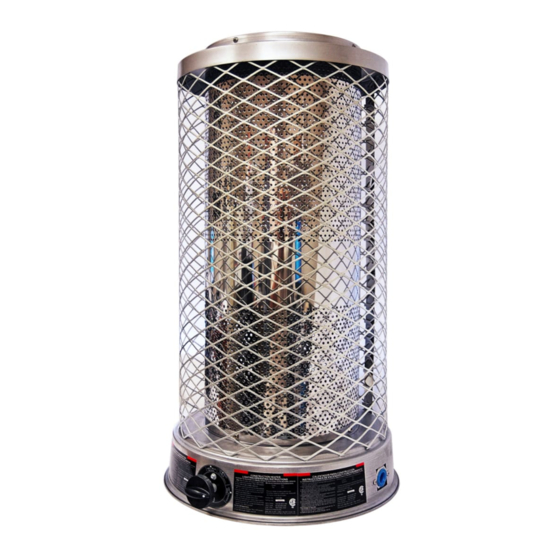
Dyna-Glo RA100NGDGD Instrukcja obsługi i instrukcja części - Strona 3
Przeglądaj online lub pobierz pdf Instrukcja obsługi i instrukcja części dla Grzałka gazowa Dyna-Glo RA100NGDGD. Dyna-Glo RA100NGDGD 13 stron. Delux natural gas radiant heaters

Dyna-Glo Delux Operating Instructions and Parts Manual
Models RA100NGDGD and RA250NGDGD
General Safety Information
(Continued)
– Check heater for damage before each
use. Do not use damaged heater.
Minimum heater clearance from
combustibles:
Sides: 6 feet
Top: 5 feet
Floor: Combustible - Not for use
on finished floors
– The heater, other than a heater with
integral propane gas container, must
be located at least 6 feet (in Canada,
distance must be 10 feet) from any
propane gas container.
– Blower or radiant type heaters shall
not be directed toward any propane
gas container within 20 feet (6 m).
– Check hose before each use of heater.
Do not use if hose is cut or damaged.
Replace with hose specified by
manufacturer.
– Always be sure to place the heater on
a stable and level surface while the
heater is in operation.
– The heater is not intended for use
on finished floors. Warping or other
damage may occur.
– Place heater away from any breezes
or drafts. Keep away from dripping
water or rain.
– Keep small children and animals away
from the heater.
– Never handle, move or service a hot or
operating heater. Wait 20 minutes after
turning heater off before touching the
heater. Severe burns can result.
– Always wear gloves when handling
the heater to prevent injury.
– Never attach ductwork to heater.
– Do not alter heater. Keep heater in its
original state.
For Technical Support or Troubleshooting, Call: 1-877-447-4768, 8:00 am - 5:00 pm CST
– Do not use heater if altered.
– Turn off gas supply to heater when
not in use.
– Use only original replacement parts.
This heater must use design specific
parts. Do not substitute or use generic
parts. Improper replacement parts
could cause serious or fatal injury.
Assembly
MODEL RA100NGDGD
1. Provide natural gas supply system.
2. Install plumbing to a low pressure
natural gas source to heater. The
source must be regulated to 1/2 PSI,
maximum 3/4 inch I.D. pipe or flexible
connector, not longer than 10 feet.
3. Be sure to use thread sealing
compound when connecting the hose
to the heater at the 1/2 NPT fitting at
the regulator inlet. Tighten all fittings
with a wrench.
4. Open natural gas supply valve
SLOWLY.
5. Check all connections for leaks.
Figure 2 – Pipe and Valve Inlet
Never use an open
flame to check for a
leak. Apply 50/50 mixture of liquid soap
and water to all joints. Bubbles forming
show a leak. Correct all leaks at once.
6. Close natural gas supply valve.
3
NEVER LEAVE THE HEATER
UNATTENDED WHILE BURNING!
Figure 3 – Heater Control Knob –
RA100NGDGD
MODEL RA250NGDGD
1. Insert AA battery (included)
into ignition by turning
COUNTERCLOCKWISE
unscrewing ignition cap.
2. Provide natural gas supply system.
3. Install plumbing to a low pressure
natural gas source to heater.
4. Connect gas supply to heater using
minimum 3/8" ID pipe. Maximum
pipe length is 10 feet.
5. Connect hose or plumbing to 1/2"
NPT flare fitting at the valve inlet.
Tighten all fittings with a wrench.
6. Open natural gas supply valve
SLOWLY. Check all connections for
leaks. Never use an open flame to
check for leaks.
7. Close natural gas supply valve.
NOTE: Keep hands and face away from
outlet (around top of shelf) of heater
while attempting to start heater.
www.ghpgroupinc.com
E
N
G
L
I
S
H
and
PROFESSIONAL GRADE
