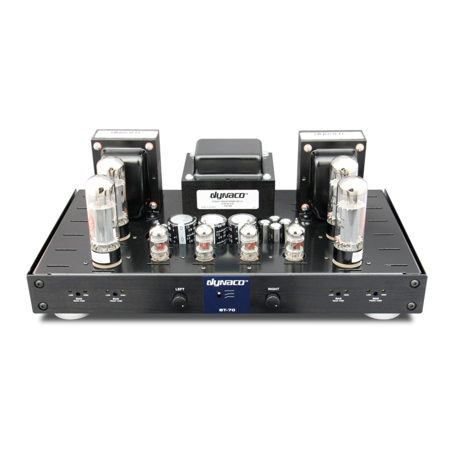
DYNACO ST-70 Instrukcja montażu - Strona 3
Przeglądaj online lub pobierz pdf Instrukcja montażu dla Wzmacniacz DYNACO ST-70. DYNACO ST-70 14 stron. Driver 6gh8 ecf82 for the ab-q-st70 auto bias module
Również dla DYNACO ST-70: Instrukcja instalacji i obsługi (9 strony)

10. Mount the quadruple section filter capacitor in the special cutout. It is IMPORTANT that the quad
cap be properly oriented. The 80 Mfd SECTION which is designated with a HALF CIRCLE must
face the BACK of the amp. Fasten by twisting each of the four mounting tabs one-quarter turn.
11. Mount your two grounding lugs in the hole just to the left of the quad cap. Mount them at a
slight angle as seen in the pictorial. Note - The color photo shows a one lug terminal strip
grounding point instead of the two grounding lugs.
12. NOTE – At this time DO NOT MOUNT the two front power takeoff sockets, the front slide switch
which fits into the stereo/mono slot or the input jacks. These three items must be mounted after
installation of the VTA driver board.
WIRING – Each length of hookup wire specified should have approximately ¼ inch of
insulation stripped from each end unless otherwise specified. Wires from the three
transformers should be shortened appropriately to the correct length to reach their terminal
point. As with the original Dynaco manual, if you see the symbol "(S)" this means to solder
that connection at that time. If the symbol is not there DO NOT SOLDER that connection at
that time. 20 gauge solid core copper wire is the recommended wire to use and need not be
pretinned with solder. If 20 gauge stranded wire is used the stripped leads should be
pretinned with solder. Only rosin core solder is recommended for soldering. Always make a
solid mechanical connection with your pliers to the terminal point before soldering. Always
keep the chassis and transformers on a soft surface like a towel so they won't get scratched.
Orient the chassis so that the power transformer is towards you. Oriented this way, the LEFT
channel is on your LEFT and the RIGHT channel is on your RIGHT.
1. Twist the pair of WHITE leads from the power transformer together and dress to socket V1.
Connect one lead to pin #2 of V1 (S) and one lead to pin #8 of V1.
2. Twist the pair of RED leads from the power transformer together and dress to socket V1. Connect
one lead to pin # 4 of V1 (S). Connect the other lead to pin # 6 of V1 (S)
3. Twist the pair of GREEN leads from the power transformer together and dress to socket V2.
Connect one green lead to pin # 2 of V2 and one green lead to pin # 7 of V2.
4. Twist the pair of BROWN leads from the power transformer together and dress to socket V7.
Connect one brown lead to pin #2 of V7 and the other brown lead to pin #7 of V7.
5. Twist the BROWN/YELLOW and GREEN/YELLOW wires from the power transformer and dress to
the 7 lug terminal strip. Connect the BROWN/YELLOW lead to lug # 7 - the lug closest to the
power transformer. Connect the GREEN/YELLOW wire to lug # 5.
6. Connect the RED/YELLOW lead to one of the grounding lugs next to the quad cap filter capacitor.
7. Dress the RED lead from the LEFT OUTPUT TRANSFORMER and the RED lead from the RIGHT
OUTPUT TRANSFORMER to the 80 Mfd terminal on the QUAD CAP having the HALF-CIRCLE
symbol. This is the terminal that faces the REAR of the amp.
8. Twist together the two CHOKE leads. Connect one choke lead to 80 Mfd terminal on the quad cap
having the HALF-CIRCLE symbol and the other choke lead to the 40 Mfd terminal on the quad cap
having the SQUARE symbol.
9. Dress the two BLACK leads from the power transformer around the power transformer as shown
in the pictorial. Connect one BLACK lead to lug A of the fuse post (S) and one BLACK lead to lug
# 1 of the on/off switch (S).
