CEL-MAR ADA-4010A Podręcznik użytkownika - Strona 7
Przeglądaj online lub pobierz pdf Podręcznik użytkownika dla Konwerter mediów CEL-MAR ADA-4010A. CEL-MAR ADA-4010A 13 stron. Rs-485/rs-422 to rs-232 addressable converter
Również dla CEL-MAR ADA-4010A: Podręcznik użytkownika (16 strony)
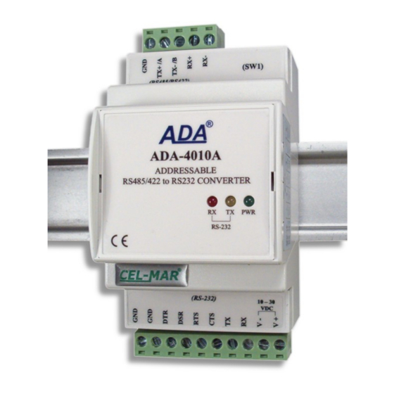
ADA-4010A
3.3.3. LINE TERMINATION Rt
Line Termination (terminator) Rt = 120 Ω let reduce influence of reflect in long lines and by hight baud rate. It is not needed below
9600Bd but for distance upper then 1000m and
transmission will be incorrect. Example of connection resistor Rt is shown on fig.5 and fig.6.
Two resistors Rt=120 Ω , 5%, 0,25W is delivered with ADA-4010A.
3.3.4. SLAVE DEVICE CONNECTION
Connection of SLAVE device to ADA-4040A is shown on fig.5 and fig.6.
3.4. POWER SUPPLY CONNECTION
To connect power supply to converter you should have DC power supplies (regulated) output voltage from 10 V= to 30V=, min.
nominal power 2W, e.g. ZS-12/250 or ADA-SPS240040D. Power cable from DC power supplies to device can not be longer than 3m.
You should connect positive (+) end of DC power supplies to Vss+ device terminal and negative (-) end to Vss- on terminal block.
ADA-4010A has protection against power supply reverse connection and if after connection power supply on front panel will not
lighting green led PWR, You should check correctness of power supply connecting (polarization).
4. ACIVATION
You can power on the unit after properly connection according to section above. If connection was made properly green LED PWR on
front panel of converter should lighting. When data is present the LEDs Tx and Rx should blink.
4.1. DESCRIPTION OF SIGNALLING LEDS
LED
PWR
Signalling of Power Supply
RX
Signalling of data receiving through ADA-4010A converter from RS232 port.
TX
Signalling of data transmitting from ADA-4010A converter through RS232 port.
LED by SW1 Blink with frequency1 Hz - signalling of configuration mode (see micro-switch SW1 setting).
LED by SW1 Blinking - signalling data flow of software to converter.
At baud rate above 38.4 kbps the LED's Tx, Rx will light weakly during data transmission
4.2. PROBLEMS'S ELIMINATION
Problem
PWR led not light
Tx led light continuously
Tx led light continuously
No transmission,
Tx led blinking.
5. CONFIGURATION
5.1. CONVERTERS OPERATION MODE
ADA-4010A converter can operate in few modes as:
● normal operating,
● configuration,
● firmware emergency updating,
This mode can be set by use SW1 switch located by RS455/RS422 terminal block after removing terminal cover marked as SW1.
Figure 1 present the location of two-position SW1 micro-switch inside ADA-4010A.
All available adjusting the SW1 switch are shown in table bellow.
Table 1. Converters operation mode
SW1- 1
SW1- 2
OFF
OFF
ON
OFF
ON
ON
9600Bd or 700m and 19200Bd you should use the Line Termination if the
Check polarization and parameters of connected power supply.
RS485(4W) / RS422 bus. Wrong polarization on Rx+, Rx- terminals. Change polarization
RS485(2W) bus. Wrong polarization on Tx+/A, Tx-/B terminals. Change polarization
RS485(4W) / RS422 bus. Check connection correctness of Tx, Rx terminals according to
chapter 3.
Operating mode
Normal operating
Device configuration
firmware emergency updating mode
Description
Normal Operating
Configuration
Software updating
ATTENTION!
Solutions
7