GAI-Tronics PHP400 Projekt, instalacja i instrukcja obsługi - Strona 7
Przeglądaj online lub pobierz pdf Projekt, instalacja i instrukcja obsługi dla Telefon alarmowy GAI-Tronics PHP400. GAI-Tronics PHP400 20 stron. Analogue version (1090/1099 series) with ampetronic hls-dm2 induction loop amplifier 230v ac power supply
Również dla GAI-Tronics PHP400: Instrukcja instalacji i obsługi (20 strony), Instrukcja instalacji i obsługi (20 strony)
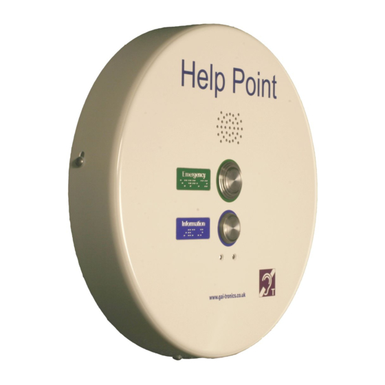
Units dimensions and weight
4.2.
Overall diameter
Depth (rear surface to front face)
Pushbutton height from front face
Unit weight
Mounting centres
Cable entries
Opening the Unit
4.3.
To open the case, undo the 4 security screws around the edge of the unit. These
screws are normally Torx type with a centre security pin.
The front section is fitted over the rear section and can be gently lifted clear.
Take care when separating the 2 sections – there are 4 cable sets between the 2 halves:
5. Induction loop audio (2 conductors)
6. DC power (2 conductors)
7. Earth cable
8. Ethernet cable.
These cables are deliberately short, but will allow the front section to sit to the left of the rear
for set-up purposes if required.
Installation method
4.4.
The Help Point is intended for vertical installation to a solid wall or suitable post as detailed
below.
1. Ensure the Help Point has been configured for the network as described in section
3.2.
2. Choose a suitable location for the Help Point, bearing in mind the weight of the unit,
and that the operating button(s) should normally be in the range 1200 – 1400mm
from the ground for ease of access by people in wheelchairs.
3. Mark the wall or surface with fixing centres as shown above. If necessary use the
rear section to help mark the centres. Do not use the rear section as a drilling
template.
405mm
88mm
10mm
6.5kg
4 x 7mm holes on 145 x 270mm centres,
see drawing 112-11-0081-001 appended to
this manual.
5 off 20mm gland entry points are provided,
with blanking plugs to blank off any that are
not used:
2 x rear
2 x lower
1 x upper (used for aerial)
Positions are detailed on drawing
112-11-0081-001 appended to this manual.
400mm VoIP Help Point, 48V VoIP.
7