Gama Sonic GS-105B-FPW Instrukcja obsługi - Strona 3
Przeglądaj online lub pobierz pdf Instrukcja obsługi dla Oświetlenie zewnętrzne Gama Sonic GS-105B-FPW. Gama Sonic GS-105B-FPW 4 stron. Solar lighting
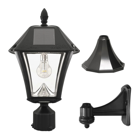
Assembly Instructions:
Post/3"Fitter Mount
Note: If you are replacing an existing gas/electric
post light, you must consult a certified technician
to disconnect them before installation.
1. Attach the fixture (D) to the base (H) with the
four supplied screws, as shown on the right.
2. Install the lamp onto your existing 3" post, using
the screws provided
Pier/ Flat base
Note:There are specific types of screws for
specific surfaces. If unsure of the appropriate
type of screw to use on your desired surface,
please consult a professional.
1. Use a drill to make two holes in the desired
surface.
2. Place the screw anchors into the holes, place
the lamp in line with the holes and secure
with the provided screws.
3. Attach the base (H) to the Pier Mount (G)
with the nut (Fig.1).
4. Attach the fixture (D) to the base (H) with
the four supplied screws, as shown (Fig.2).
Wall Mount
1. Use a drill to make two holes in the desired
surface.
2. Place the screw anchors into the holes, place
the lamp in line with the holes and secure
with the provided screws.
3. Attach the base (H) to the Wall bracket (F)
with the nut (Fig.3).
4. Attach the fixture (D) to the base (H) with
the four supplied screws, as shown (Fig.4).
Operation
Instructions
page 3
1. Remove the Top (B) by unscrewing the 2 screw caps.
Screw the GS LED lightbulb into the socket. Turn on switch
to desired setting high or low (for longer duration). The
Solar Lamp will automatically operate at dusk.
After assembling your specific bracket
here are the steps to finish assembling
your unit, this step applies to all three
brackets:
1.
Place the
lens and cone (C)
in the body (D).
2.
Screw the GS
LED lightbulb into
Fig. 1
the socket. Turn on
switch to desired
setting.
Fig. 2
3.
Attach top
(B) to the body
(D) with the two
Fig. 3
supplied screw
caps.
Fig. 4
2. Reattach the Top (B) and
secure with the 2 screw caps.
Operation Switch
4.
Screw the finial
(A) on top