Alke Global-8 Series Instrukcja obsługi i instalacji - Strona 4
Przeglądaj online lub pobierz pdf Instrukcja obsługi i instalacji dla Grzałka Alke Global-8 Series. Alke Global-8 Series 17 stron.

General information
Model identification
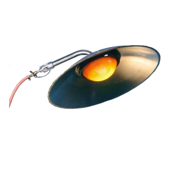
The main identification of the different models is Global-5 and Global-8. These are independent
atmospheric stainless steel infrared heaters. Suffixes are used behind these model names to add
additional type information about the models (e.g. Global-5 CETETHi).
CE:
that particular type is CE approved
DS:
equipped with a dual dust filter connection
TE:
equipped with a thermocouple safety device
TH:
equipped with an independent thermostat and remote sensor (1,25 meter long)
THi:
equipped with an independent thermostat and integrated sensor
DI:
double injection system
MK:
solenoid valve for hi-low application on 24VAC or 230VAC
Packaging
Normally (depending model and order quantity) the heaters are packed per 1, 2 or 4 in a box. Always
check the heaters for transport damage directly after receiving them. Note that the heaters will be a bit
discoloured by temperature due to a 5 minutes quality check after manufacturing.
The heaters are pre-assembled. In some cases, if there is a risk for damaging during transport, the
thermocouple sensor is separated from the gas safety device. Re-assembly can be simply done by
screwing the M8 nut (18) of the sensor back on the safety device (17). Do not tighten too strong.
In most cases the reflector is delivered separately from the burner part to save on transport costs.
Reassembly is easy: move the burner tube through the hole in the reflector. Slide the reflector over the
tube till it rests on the upper plate of the burner. Secure the reflector with 4 nuts and washers and 2 eye
bolts.
The thermostat knob is always delivered separated from the thermostat valve.
1) Remove the protection cover from the thermostat valve.
2) Turn the knob on maximum temperature and push the knob on the valve.
3) Fix the knob by turning the large metal screw ring till it stops (at least 2 turns, hand tight).
For thermostats with a remote sensor only: bend the sensor line carefully (no sharp bends) to the
thermostat valve and secure the sensor line with a ty-rap around the red protection lining and the
thermocouple safety device (see picture). Note that the tubing is hollow, a sharp bend will close the
tubing and makes the sensor worthless. The chance of breaking the line at the entrance of the
thermostat knob is largely limited now.
Version: April 2016
4
manual number: 0009 0440EN
