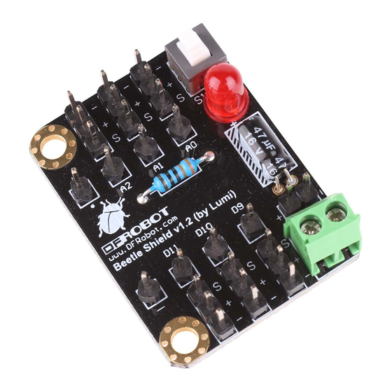
DFRobot Beetle Shield Skrócona instrukcja obsługi - Strona 2
Przeglądaj online lub pobierz pdf Skrócona instrukcja obsługi dla Płyta główna DFRobot Beetle Shield. DFRobot Beetle Shield 4 stron.

Specification
Operating voltage: 3 - 5V
Compatible with DFRobot Beetle
Attaching the Beetle controller to the Beetle shield
Note: For Beetle shield versions lower than v1.1 the label for D9 and D11 is switched. The pin
labeled with D9 on the shield goes to D11 on the Beetle and D11 on the shield is going to D9 on the
Beetle. Please take the labels on the Beetle controller as the right ones. We have fixed this error in
v1.1
To attach the Beetle to the shield it requires some soldering work. Align the holes of the Beetle with
the pins on the shield. Make sure the Beetle controller is showing the microcontroller chip and the
USB socket facing up to ensure the correct polarity and pin assignment after soldering it to the
shield.
Beetle controller on Beetle shield (click to enlarge)
Push the Beetle down onto the pins and let the pins looking out for ca. 1mm. Solder the eight pins at
the pads of the Beetle using a soldering iron or soldering gun.
Soldering the Beetle controller on the Beetle shield
