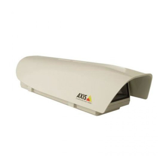
Axis T92A20 Instrukcja instalacji - Strona 7
Przeglądaj online lub pobierz pdf Instrukcja instalacji dla Akcesoria do kamer Axis T92A20. Axis T92A20 12 stron. Protective housing

AXIS T92A20 Installation Guide
Connect power and network cables to the camera
4
1. The pre-installed red (+) and black (GND) wires are used to power the camera (fig.3).
2. Connect the wires to the terminal connector on the Axis network camera (fig.4).
3. Connect the supplied RJ45 patch cable to the Data Out connector on the pre-installed High
PoE Splitter (fig.3).
4. Connect the RJ45 Patch cable to the network connector on the camera.
5. Proceed to "Route the cables to the housing" on page 9.
FIG.3
Note:
The camera models have different terminal connectors. Be sure to follow the correct description
for the installed camera (fig.4).
Red/black power cable
+ / GND
+
GND
PWR OUT
High PoE
DATA OUT
Splitter
PWR IN/POE IN
Housing connector board
Wire
Connector board
Red
DC Power (+)
Black
GND
Power to
camera
GND (black)
+12V DC (red)
Camera
Camera DC Power (+)
Camera (GND)
Page 7
