Olympus BH-2 BHTU Podręcznik - Strona 6
Przeglądaj online lub pobierz pdf Podręcznik dla Mikroskop Olympus BH-2 BHTU. Olympus BH-2 BHTU 24 stron. Sliding focus block
Również dla Olympus BH-2 BHTU: Kompletny demontaż, czyszczenie i ponowny montaż (23 strony)
extinguishing the 6V LED. If the setting of the intensity control is decreased to the point where the clamped control
signal exceeds the threshold waveform, the 6V LED will completely extinguish. The operation of the remaining three
comparators is similar to this one, differing only in their threshold voltages.
Power LED
Resistor R203 and LED "A" function as the power‐on indicator for the microscope.
Errors in the Olympus Documentation
In the course of researching this document, two errors were identified in the schematic diagram published in the
Olympus Research Microscope Series BH2 (BHS) Repair Manual. Both of these errors are in the LED bar‐graph display
circuitry.
Bar‐Graph LEDs
The first error is in the wiring of the four bar‐graph LEDs, as shown in Detail 1 of Appendix 2 and Appendix 3 of this
document. The Olympus manual shows these LEDs wired with their cathodes connecting to their respective comparator
outputs and with their anodes wired to their respective current‐limiting resistors. The actual circuit configuration (as
observed on the main boards of functional BHTU equipment) has the anodes of the four LEDs connected to the filtered
DC power supply line and the cathodes connected to their respective current‐limiting resistors. This is a minor
discrepancy and either configuration would work equally well, but the actual as‐built configuration is shown in this
document.
Control‐Signal Clamping Network
The second error is in the wiring of the control‐signal clamping network, as shown in Detail 2 of Appendix 2 and
Appendix 3 of this document. The Olympus manual shows this network fed from the full‐wave‐rectified output of the
bridge rectifier, but in the actual circuit configuration (as observed on the main boards of functional BHTU equipment),
this network is fed from the filtered DC power supply line. This error is of greater consequence than the first, as the
circuit published in the Olympus repair manual would not guarantee that the LEDs remain off around the zero crossings
of the AC line.
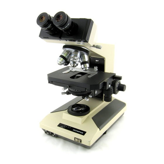
Removing the Electrical Base from the Stand
To gain access to the electronics in the base of the BHT/BHTU stand, the electrical base must be removed from the base
of the stand. Be sure to take sufficient notes and plenty of photographs both before and during the disassembly process
to make sure that everything can be correctly reassembled later on. Before removing the electrical base, look at the
right‐hand side of the unit, just above the intensity slider, and note whether or not a light preset control and switch are
present. The earlier units did not include these components, but the later ones did.
Next, remove all the major components from the microscope stand (i.e., AC power cord, condenser, stage, eyepieces,
viewing head, and objectives). Doing so will make the stand easier to maneuver and will prevent inadvertent damage to
these components during disassembly and reassembly. Be sure to protect these components from dust and damage
while they are not installed on the stand.
After removing these components, cover the top of the arm (i.e., the nosepiece turret and the exposed mounting
dovetail for the viewing head) with a clean plastic bag and secure this with a rubber band to keep dust out of these
openings. This is especially important on BHTU stands which have an optical correction lens located just below the
viewing head to correct for the difference in tube length introduced with the reversed nosepiece.
With the stand in its normal upright position, remove the lamp house from the back of the base. The lamp house simply
plugs into the base, and can be removed by grasping it and pulling it straight back. Set the lamp house aside to prevent
damage. Do not touch the halogen lamp with your fingers, as oils from your skin will cause premature failure of the
bulb. If the bulb is accidentally touched, clean it with isopropyl alcohol.
Carefully turn the stand upside down, exercising caution to prevent impacts to the focus knobs and to the
condenser/stage holder. Using a 5/32" Allen tool, remove the four hex socket‐head cap screws from the bottom of the
Olympus BH‐2 (BHT/BHTU) Electronics
Revision 2
Page 6 of 24