Axxess TRIGGER Instrukcja instalacji - Strona 2
Przeglądaj online lub pobierz pdf Instrukcja instalacji dla Elektronika samochodowa Axxess TRIGGER. Axxess TRIGGER 19 stron.
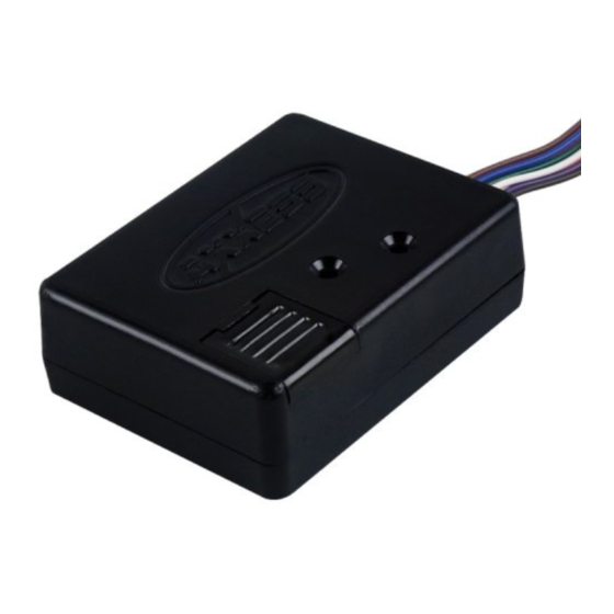
TRIGGER
Notes:
*Pin 1 needs to be attached to ground and pin 11 needs to be attached to 12 volt
constant on all configurations listed below.
* Metra recommends using a single pulse double throw relay in every application.
(Metra part # E-123)
Pin diagram
Pin 1: Black (Chassis Ground)
Pin 2: Purple (Configuration input)
Pin 3: White (Configuration input)
Pin 4: Pink (Configuration input)
Pin 5: Orange (Configuration input)
Pin 6: Green ((-) Output 500mA Max)
Pin 7: Red ((-) Output 500mA Max)
Pin 8: Blue ((+) output 2 amp Max)
Pin 9: Brown (+ 0.8- 16v input trigger)
Pin 10: Gray (- input trigger)
Pin 11: Yellow (12 volt Constant/Switched)