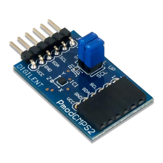
Digilent Pmod CMPS2 Podręcznik referencyjny - Strona 11
Przeglądaj online lub pobierz pdf Podręcznik referencyjny dla Akcesoria Digilent Pmod CMPS2. Digilent Pmod CMPS2 12 stron.

Pmod CMPS2™ Reference Manual
67. Cycle the SCL line to receive the data bits from the X, Y, and Z registers in the SDA line, providing an ACK
between each data byte. The Pmod CMPS2 address pointer automatically moves to each consecutive
byte. End the communication by sending a NACK followed by a STOP command.
I2CReadMultiple(6); //read six bytes, sending an ACK to the slave device betwe
en each byte received and a NACK after the last byte
68. Each of the readings will contain the external magnetic field H in addition to offset associated with the
current put through the coil by the RESET action.
69. The offset associated with the device can be calculated and then subtracted from future measurements to
obtain the actual magnetic field.
The other method of calibration is to remove the hard iron bias introduced to the magnetometer by the
surrounding environment by measuring (either continually or for a set time) all of the possible magnetometer
readings in a Cartesian sphere and keep track of the highest and lowest readings for each axis. The offset can then
be calculated in the same fashion as described above with the SET and RESET actions. The advantage of this
method is when the Pmod CMPS2 is continually changing locations or when other external magnetic fields may be
introduced into the test environment.
2.4.2 Data Conversion
The Memsic MMC34160PJ provides data for each axis in units of Gauss, but the information is generally more
legible when presented as a compass heading. The method for converting Gauss units to a compass heading is
provided below.
1.
Calculate the real Gauss value for the X and Y axes from the amount of LSBs returned where the LSB value
by default is 0.48828125 mG, resulting in 2048 LSBs per Gauss.
2. Calculate the direction D by first checking to see if the X Gauss data is equal to 0 to prevent divide by 0
zero errors in the future calculations. If the X Gauss data is 0, check to see if the Y Gauss data is less than
0. If Y is less than 0 Gauss, the direction D is 90 degrees; if Y is greater than or equal to 0 Gauss, the
direction D is 0 degrees.
3. If the X Gauss data is not zero, calculate the arctangent of the Y Gauss and X Gauss data and convert from
polar coordinates to degrees.
4. If the direction D is greater than 360 degrees, subtract 360 degrees from that value.
5. If the direction D is less than 0 degrees, add 360 degrees to that value.
6. The compass heading can then be determined by the direction value D:
Copyright Digilent, Inc. All rights reserved.
Other product and company names mentioned may be trademarks of their respective owners.
Arrow.com.
Arrow.com.
Arrow.com.
Arrow.com.
Arrow.com.
Arrow.com.
Arrow.com.
Arrow.com.
Arrow.com.
Arrow.com.
Arrow.com.
Downloaded from
Downloaded from
Downloaded from
Downloaded from
Downloaded from
Downloaded from
Downloaded from
Downloaded from
Downloaded from
Downloaded from
Downloaded from
= ∗ 0.48828125
= ∗ 0.48828125
If D is greater than 337.25 degrees or less than 22.5 degrees – North
If D is between 292.5 degrees and 337.25 degrees – North-West
If D is between 247.5 degrees and 292.5 degrees – West
If D is between 202.5 degrees and 247.5 degrees – South-West
If D is between 157.5 degrees and 202.5 degrees – South
2 = − +
2
= 1 +
2
= arctan (
) ∗
180
Page 11 of 12
