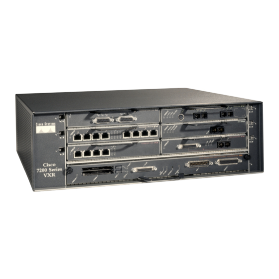
Cisco 7200 VXR Series Skrócona instrukcja obsługi - Strona 14
Przeglądaj online lub pobierz pdf Skrócona instrukcja obsługi dla Bezprzewodowy punkt dostępowy Cisco 7200 VXR Series. Cisco 7200 VXR Series 48 stron. Preparing for installation
Również dla Cisco 7200 VXR Series: Arkusz danych (12 strony), Podręcznik (14 strony)

Figure 8
Attaching the Rack-Mount Brackets to the Rear of the Chassis—Front Recessed
2
1
4
1
Rack-mount bracket
2
M4 x 8-mm Phillips flathead screws
Brackets Rear-Mounted—Front Recessed in the Rack
Step 1
Locate the threaded screw holes in the rear sides of the chassis.
Step 2
Align a rack-mount bracket (1) to the threaded holes in the right side of the chassis.
Step 3
Using a Number 2 Phillips screwdriver and two M4 x 8-mm Phillips flathead screws (2), attach the rack-mount bracket
to the router.
Step 4
Repeat Step 2 and Step 3 for the bracket on the other side of the router. If you are not installing cable-management
brackets, skip to the "Two-Post or Four-Post Rack Installation" section on page 16 for rack-mount instructions.
Otherwise continue with Step 5.
Step 5
Align a cable-management bracket (3) to the threaded holes in the front of the chassis.
Step 6
Using two M4 x 8-mm Phillips flathead screws (4), thread and tighten the screws through the cable-management
bracket and into the chassis.
Step 7
Repeat Step 5 and Step 6 on the other side of the router.
If you have an NPE-G1 or NPE-G2 installed, go to the "NPE-G1 or NPE-G2 Rear Cable-Management Brackets on a
Rear-Mounted Router" section on page 15, or the "NPE-G1 or NPE-G2 Optical Cable-Management Bracket" section on
page 16.
If you do not have an NPE-G1 installed, go to the "Two-Post or Four-Post Rack Installation" section on page 16.
14
Cisco 7200
Series
3
TOKEN RING
ETHERNET 10BT
ETHERNET-10BFL
FAST ETHERNET INPUT/OUTPUT CONTROLLER
3
Cable-management bracket
4
M4 x 8-mm Phillips flathead screws
