Cisco UCS E Series Instrukcja instalacji - Strona 39
Przeglądaj online lub pobierz pdf Instrukcja instalacji dla Serwer Cisco UCS E Series. Cisco UCS E Series 46 stron. Ucs e series unified computing system
Również dla Cisco UCS E Series: Przegląd produktów (8 strony), Instrukcja rozwiązywania problemów (28 strony)

Ultimate disposal of this product should be handled according to all national laws and regulations.
Warning
Statement 1040
No user-serviceable parts inside. Do not open. Statement 1073
Warning
Warning
This unit might have more than one power supply connection. All connections must be removed to
de-energize the unit. Statement 1028
Warning
Blank faceplates and cover panels serve three important functions: they prevent exposure to
hazardous voltages and currents inside the chassis; they contain electromagnetic interference (EMI)
that might disrupt other equipment; and they direct the flow of cooling air through the chassis. Do not
operate the system unless all cards, faceplates, front covers, and rear covers are in place. Statement
1029
This section includes the following topics:
•
•
•
Memory DIMM Location
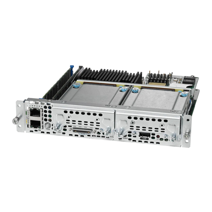
The following figure shows the location of the memory DIMMs in a single-wide E-Series Server.
The single-wide E-Series Servers support up to 16 GB of DDR3 memory DIMMs.
Note
Figure 18
Node0_Dimm1
OL-26447-03
Memory DIMM Location, page 39
Removing the Memory DIMM, page 40
Installing the Memory DIMM, page 41
Memory DIMM Location in a Single-Wide E-Series Server
Node0_Dimm0
Installing and Replacing the Memory DIMMS
Hardware Installation Guide for Cisco UCS E-Series Servers
39
