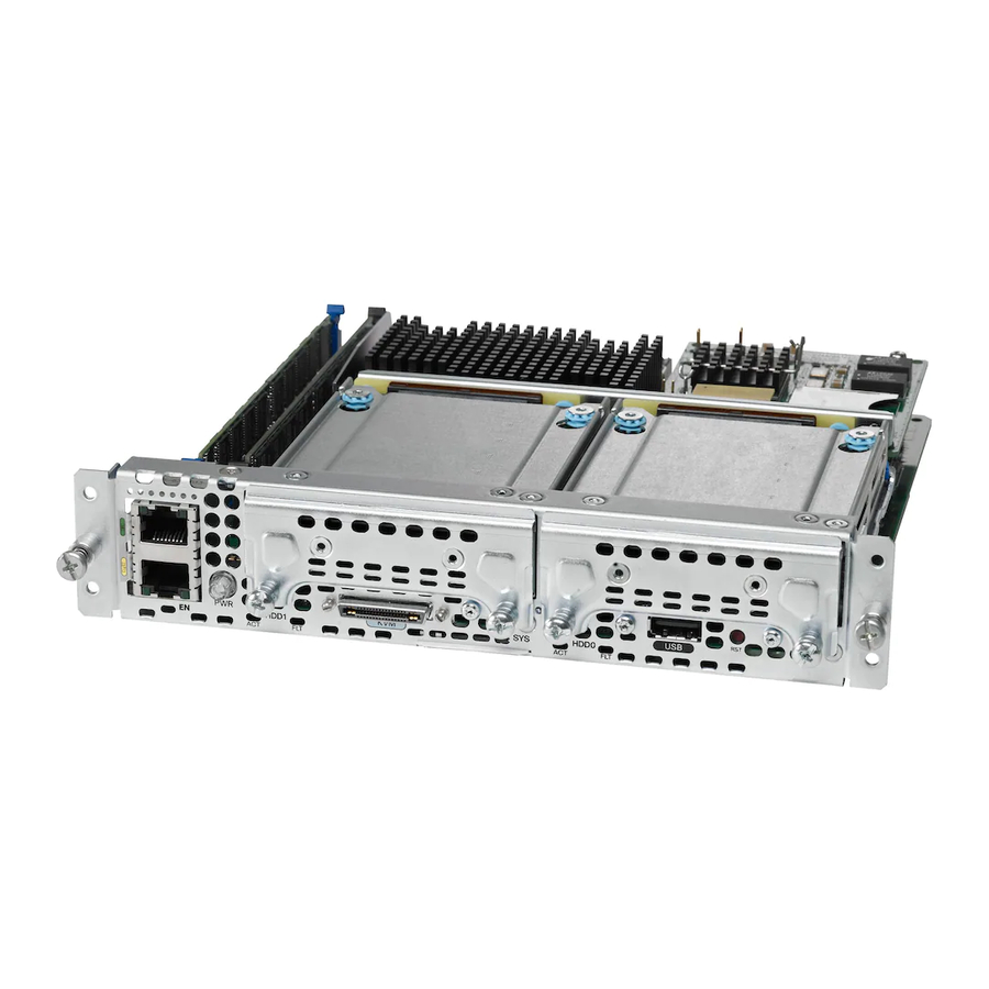
Cisco UCS E Series Instrukcja instalacji - Strona 42
Przeglądaj online lub pobierz pdf Instrukcja instalacji dla Serwer Cisco UCS E Series. Cisco UCS E Series 46 stron. Ucs e series unified computing system
Również dla Cisco UCS E Series: Przegląd produktów (8 strony), Instrukcja rozwiązywania problemów (28 strony)

Installing and Replacing the Memory DIMMS
DIMMs must be installed in the following order in the double-wide E-Series Servers:
Note
DIMM 1 (center DIMM)
1.
DIMM 2 (closest to the CPU)
2.
DIMM 0 (outboard DIMM)
3.
DIMMs must be installed in the following order in the single-wide E-Series Servers:
Note
DIMM 0 (closest to the CPU)
1.
DIMM 1 (outboard DIMM)
2.
Procedure
Step 1
Connect the wrist strap clip to an unpainted portion of the chassis frame to channel unwanted ESD
voltages to ground.
Turn off power to the router.
Step 2
Note
Locate the DIMM connector. See the
Step 3
Note
Make sure that both latches on the DIMM connector are in the open position.
Step 4
Orient the DIMM so that the polarization notch on the DIMM lines up with the notch on the connector.
Step 5
See the following figure.
Figure 21
1
Polarization notch
Insert the DIMM into the connector.
Step 6
Hardware Installation Guide for Cisco UCS E-Series Servers
42
Alternatively, the Cisco 3900 ISR G2 and the Cisco ISR 4451-X support OIR. See the
Insertion and Removal" section on page
The DIMM connectors on the double-wide E-Series Servers are positioned at an angle;
therefore, make sure that you insert the DIMM at approximately the same angle.
Polarization Notch on the DIMM
29.
"Memory DIMM Location" section on page
1
"Online
39.
OL-26447-03
