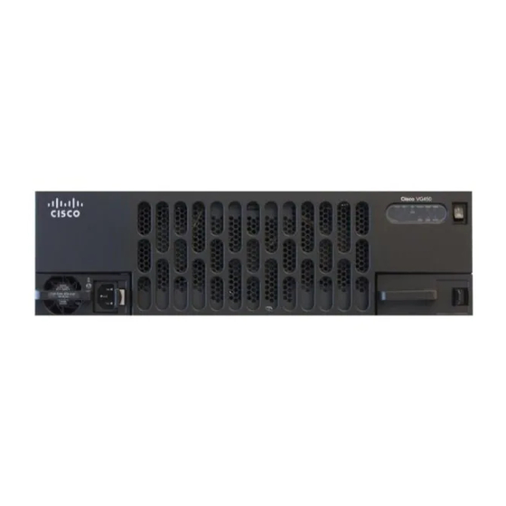
Cisco 450 Instrukcja instalacji sprzętu - Strona 23
Przeglądaj online lub pobierz pdf Instrukcja instalacji sprzętu dla Gateway Cisco 450. Cisco 450 37 stron. Voice gateway

Installing the Cisco VG450 Voice Gateway
• Screws and anchors for wall-mounting, if required
• ESD-preventive wrist strap
In addition, you might need the following external equipment:
• Console terminal or PC with terminal emulation software
• PC running terminal emulation software for administrative access
• Modem for remote access
• Analog voice RJ-21 cable
• Ethernet switch
• Modem for remote configuration
Unpacking and Inspection
Do not unpack the Cisco VG450 until you are ready to install it. If the installation site is not ready, keep the
chassis in its shipping container to prevent accidental damage.
The Cisco VG450, cables, printed publications, and any optional equipment you ordered might be shipped in
more than one container. When you unpack each shipping container, check the packing list to ensure that you
received all the following items:
• Cisco VG450 Voice Gateway
• Power cord, 6-foot (1.8-meter)
• RJ-45-to-DB-25 adapter cable (labeled Console)
• RJ-45-to-DB-9 adapter cable (labeled Auxiliary)
• Rack-mounting brackets for 19-inch rack (one pair) with screws for attaching to chassis
• Chassis guard for wall-mounting applications
• Grounding lug and fasteners
Inspect all items for shipping damage. If anything appears damaged, or if you encounter problems when
installing or configuring your system, contact a customer service representative.
Installing Cisco VG450 Voice Gateway
SUMMARY STEPS
1. Shut down the electrical power to the slot in the router either by turning off the electrical power to the
router or by issuing the online insertion and removal (OIR) commands. Leave the power cable plugged
in to channel ESD voltages to ground. For more information on OIR, see the "Managing Cisco Enhanced
Services and Network Interface Modules" chapter in the Cisco 4000 Series ISRs Software Configuration
Guide .
2. Remove the blank faceplates installed over the network interface module slot that you intend to use.
• Eight wood screws or other fasteners, for installing the chassis on a wall. An additional starter screw
can be used to facilitate wall-mounting.
Cisco 450 Voice Gateway Hardware Installation Guide
Unpacking and Inspection
21
