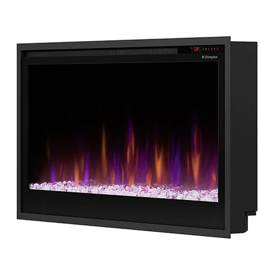
Dimplex 6910470100 Instrukcja serwisowa - Strona 15
Przeglądaj online lub pobierz pdf Instrukcja serwisowa dla Kominek wewnętrzny Dimplex 6910470100. Dimplex 6910470100 17 stron.

Media LED Replacement
Tools Required: Phillips Head Screwdriver
1. Follow the instructions for Preparing the Firebox for Service on page 6.
2. Remove the 2 screws on each side of the bottom panel (4 total). Disconnect the LED connection. (Figure 17,
page 13) The media LED boards are located on the underside of the bottom panel.
3. To release the media LED board, insert a screwdriver in the center of each rivet to separate the pin from the base.
Set aside the pin and base of each rivet, as well as the circular standoffs. (Figure 22)
4. Disconnect the defective LED board.
5. Connect the new LED board, ensuring the J1 marking is oriented toward the right.
6. Position the new LED board.
7. Align the holes on the bottom panel, circular standoff, and LED board and insert the sleeve of the rivet. Insert the pin
from the rivet through the sleeve to secure the rivet.
8. Secure the bottom panel, ensuring that the right-side LED is reconnected through through the square opening.
9. Reassemble firebox.
Figure 22
15
