FirePro FPC-2 Instrukcja obsługi i konserwacji - Strona 7
Przeglądaj online lub pobierz pdf Instrukcja obsługi i konserwacji dla Kontroler FirePro FPC-2. FirePro FPC-2 7 stron. Fire control panel system isolation
Również dla FirePro FPC-2: Instrukcja obsługi i instalacji (14 strony), Instrukcja obsługi i konserwacji (8 strony), Skrócona instrukcja obsługi (2 strony)

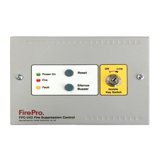
5. Panel Operation
Silence Alarms
Silence/Sound alarm
The
Reset
Reset
To
button is a full reset on the FPC-2 panel only.
6. Power supply
The control panel requires 24v DC.
Exceeding the maximum power supply rating may cause a fuse or other protective device to operate and render
the equipment inoperative until the fuse is replaced or protective devices are reset.
7. Maintenance
FPC-2 control panels do not require any specific maintenance but should the control panel become dirty it can be
wiped over with a damp cloth and should then be dried with a dry, lint free cloth. Detergents or solvents should
not be used to clean the panel and care must be taken that water does not
Testing of the extinguishant system should only be carried out by trained personnel and must be done with
appropriate isolation measures in place to ensure that accidental discharge of the extinguishant agent is avoided
and any malfunction should be reported to the fire alarm maintenance company immediately.
8. Commissioning & Testing
Before applying power to the panel, igniting actuators must be physically isolated from the system by disconnecting
both wires to it. This will prevent any accidental release of extinguishant.
When power is applied, if all connections are correct, only the green Power should be lit. If any fault indicators
are lit the wiring to the appropriate input or output should be checked and all faults have been cleared before
proceeding.
TESTING
DISCONNECT ALL FIREPRO AEROSOL GAS GENERATORS BEFORE TESTING.
Do not leave any FirePro gas generators connected to the unit when testing or these units will activate.
TO TEST SYSTEM:
Step 1 Turn Power off
Step 2 Disconnect FirePro units and connect test lamps
Step 3 Visually inspect each FirePro unit installed and
ensure BKF and mounting bolts are intact. The
FirePro® unit must be clean and free of debris
Step 4 Inspect all other component detectors, sirens
etc. Inspect cable for any signs of damage.
Step 5 Turn power on to panel and test detection
system to simulate activation-all test lamps to
be lit.
Step.6 Turn off power – Reconnect all FirePro units
Step.7 Turn power on – Testing is complete
Note: If the system has been activated the system activation fuse needs to be inspected as blown fuse will show
as a fault. The Fuse is 1.6AMP Quick Blow.
fp_c2_m5.3
button will only silence the buzzer in the FPC-2 unit.
Enter
the enclosure.
Page 7 of 7
