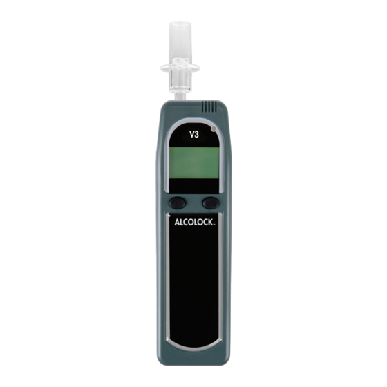
Alcolock V3 Instrukcja instalacji - Strona 6
Przeglądaj online lub pobierz pdf Instrukcja instalacji dla Sprzęt testowy Alcolock V3. Alcolock V3 8 stron. Series b-2, 12v & 24v ecu

UNINSTALLATING THE ECU
To be done only when removing the ECU from the vehicle.
1.
Disconnect all wires that come from the ECU wiring harness and are connected to different
parts of the vehicle electrical system. Unsolder all connections and tape the wires.
2.
Disconnect the terminal ring (which is connected to the black ground wire in the wiring
harness) from the ground point on the vehicle (the connection was made with a metal crimp
ring and nut).
3.
Locate the wire that was cut during installation. This wire was part of the vehicle's main
harness and it ran between the ignition switch and the starter relay or solenoid. Reconnect
the wire.
4.
Once the ECU is uninstalled (the above 3 steps), attempt to start the vehicle engine by
turning the ignition switch.
DISPOSAL AT END OF SERVICE LIFE
To dispose of the ALCOLOCK V3 device (ECU, handset, or both) when it is deemed to be at the
end of its service life:
• Return the device to the dealer for disposal
• Contact the local waste management authority for more information
• Ask a suitable disposal contractor to dispose of the device
WIRING TABLE
COLOUR
Red
Black
White
Blue (2 wires)
Blue / Yellow (2)
Green
Yellow / Red
Blue / White
Pink
Brown
4
LOCATION
+12 or +24 volts, un-switched, fused 10A
Ground
Ignition switch
To starter
From ignition switch
Engine run signal
CAN bus 1
CAN bus 2
Wake up signal (connected to vehicle parking lamps)
(+) AUX lamp
REQUIRED
Yes
Yes
Yes
Yes
Yes
Yes
Optional
Optional
Optional
Optional
ALCOLOCK V3 SERIES B-2
