Clarke Woodworker CS6-9C Instrukcja obsługi i konserwacji - Strona 7
Przeglądaj online lub pobierz pdf Instrukcja obsługi i konserwacji dla Sander Clarke Woodworker CS6-9C. Clarke Woodworker CS6-9C 15 stron. Belt & disc sander belt & disc sander

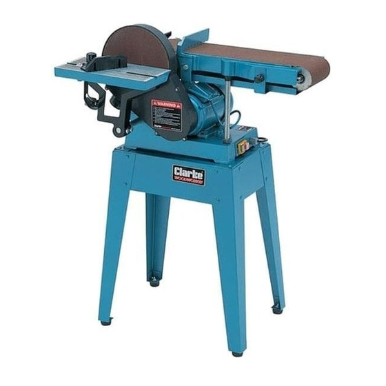
ASSEMBLY
1.
Assemble the stand in the manner shown in Fig.2.
The four top panels are secured with a single bolt,
with flat washer, in each corner, and the legs are
then bolted on, followed by the leg braces.
Do not tighten the nuts until all bolts are in place
and the stand is rocked vigorously to ensure it is
stable. When satisfied, tighten securely.
2.
WITH ASSISTANCE, considering its
weight, raise the machine and
place it on top of the
stand.
Manoeuvre it so that the
bolt holes, viewed from
below, line up. Enter the
M6 screws fitted with flat and
lock washers and tighten securely.
3.
Screw the Belt Tensioning Lever (see Fig.4) securely into its housing.
NOTE:
Except for the table, your Sander is now fully assembled. The location of the Table will depend
upon the job in hand, i.e. either adjacent to the disc or the belt. Table fitting and adjustments
are described on pages 8 and 9.
The machine is fitted with a Sanding Disc and Sanding Belt at the factory.
CHECKS BEFORE USE
As with all machinery, it is important to ensure that the various components are properly
secure and in good order before use.
The machine is designed so that when switched ON, both the belt AND the disc will rotate.
It is also important therefore, to ensure that the belt runs true on the rollers, referred to as
'Tracking'. Although the necessary adjustments have been carried out at the factory, it is
nevertheless prudent to perform this check when first setting up your machine, in the event
it has been disturbed during transit.
Belt Tracking Check
The rollers must run parallel, otherwise the
belt will be driven off to one side. To
perform the check, ideally the belt
should be in the vertical position, as this
position provides greater safety for the
operator.
To raise the belt to its vertical position,
slacken off the two securing screws, one
of which is shown in Fig. 3, the other is
diametrically opposed. Then raise the
arm, and retighten the two screws.
Fig.2
- 7 -
Fig. 3
