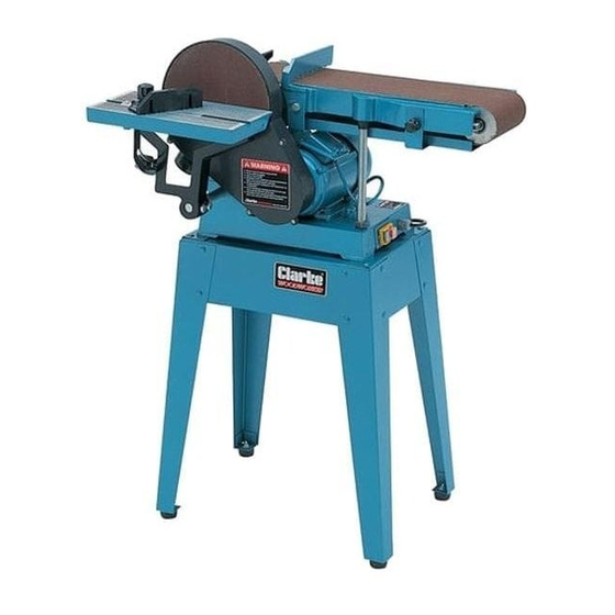
Clarke Woodworker CS6-9C Instrukcja obsługi i konserwacji - Strona 8
Przeglądaj online lub pobierz pdf Instrukcja obsługi i konserwacji dla Sander Clarke Woodworker CS6-9C. Clarke Woodworker CS6-9C 15 stron. Belt & disc sander belt & disc sander

With the belt raised, ensure that nothing can interfere
with the disc or belt, and that the Belt Tensioning Lever
(1, Fig.4), is pushed fully to the rear - in the direction
of the arrow.
Plug in to the mains supply and press the GREEN ON
button, marked 'I' to start the machine. keeping well
away from the belt.
Observe the belt as it passes over the front (top)
roller....there should be no creep to one side. If it does
creep, switch OFF by pressing the RED OFF button,
marked 'O'.
Adjacent to the belt tensioning lever, is the Roller
Adjustment Knob (2, Fig.4). Slacken the locknut as
shown in fig. 4 and back the nut off a turn or two.
Restart the machine, and screw the Adjuster Knob
very gently in or out to compensate for the creep.
When the belt is running true, switch OFF and tighten
the locknut, ensuring you do not allow the adjuster knob to turn. When satisfied, restart and
check. If necessary, repeat until the belt runs true.
FITTING THE TABLE
A ...to the Disc
The Table is mounted on a Support Bar (6, Fig.1 and 1, Fig.5). 'Flats' are milled at each end
of the bar. Insert the end with the shorter length flat into the housing on the machine.
NOTE: It may be necessary to unscrew the two securing screws (2,Fig.5) in order for the bar
to be inserted fully.
Tighten the securing screws.
Slide the table assembly on to the
support bar, and bring the table to within
2mm of the disc, then tighten the two
securing screws (1, Fig.6).
To ensure the table is at exactly 90
the disc, place a small engineers square
on the table and bring up to the disc.
Slacken off the Table Angle Adjustment
Knob, shown in Fig.5, and adjust
accordingly so that the table is true.
Tighten the adjustment knob, and if
necessary, zero the pointer, adjacent to
the scale, by slackening the securing
screw and repositioning.
o
to
- 8 -
Fig. 4
Fig. 5
