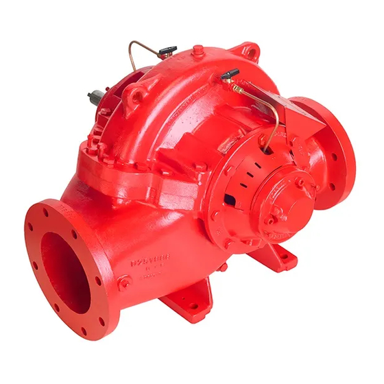
Armstrong 4600 HSC series Instrukcja instalacji i obsługi - Strona 8
Przeglądaj online lub pobierz pdf Instrukcja instalacji i obsługi dla Pompa wodna Armstrong 4600 HSC series. Armstrong 4600 HSC series 16 stron. Horizontal split case fire pumps. 12x8x18f

i n s ta l l at i o n &
o p e r at i n g i n s t r u c t i o n s
8
2.0. operation-electric driven
set pressure switches to the following
setting values:
• Fire Pump Stop Point (fsp)
Off Pressure + min. Static Suction Pressure
• Jockey Pump Stop Point (jsp)
• Jockey Pump Start Point (jstrt) jstrt = jsp - 10 psi
• Fire Pump Start Point (fstrt)
2.1. prestart-up
Fill out prestart-up check list
2.2. pressure switch setting
The pressure switch to start the fire pump is normally located
in the lower left-hand side of fire pump controller. Similarly
the pressure switch to start the Jockey pump is located in the
Jockey pump controller.
Make sure pump shutoff + max. suction pressure does not ex-
ceed system rated pressure or its components. If it does, a main
relief valve should be installed at the pump discharge.
2.3. circulation relief valve
The circulation relief valve should be set in the field at pressure
to the lowest suction pressure, plus the rated pressure of the
unit raised to the next higher 5 lbs increment.
2.4. start-up procedure - (pump sequence)
caution: In case of electrical control circuit problem
use the emergency disconnect lever to bypass control
circuits
a. electric driven
• Open suction gate valves
• Check that pump is full of water and that all air contained
in pump has been allowed to escape through the air
release valve
• Compress packing evenly with gland (gland nut should be
finger tight)
• Lower setting of pressure switch (senses discharge pressure)
to prevent pump from starting
• Place the main disconnect switch in the on position
• Place circuitry breaker in the on position and check if power
on light is illuminated
Horizontal split case
fire pumps
fsp
= Fire Pump Shut
jsp
= fsp
fstrt = jstrt - 5 psi
• Check direction of driver rotation by pressing momentarily
the start and then stop push buttons on the controller (prop-
er direction is indicated by arrow on pump casing); for in-line
pump use a light on shaft to see rotation (this is clockwise
looking down from top of motor). If rotation is wrong inter-
change motor leads in panel per instructions in panel
• Bring the timer setting down to one (1) minute for automatic
start test purpose
• Open system butterfly valve
• Bleed the system by opening a valve on the pressure sensing
line to create a pressure drop
• As soon as fire pump starts check if full load current value is
within the electric motor nameplate rating with service factor
taken into account
• Check packing adjustment to obtain slight leak of approxi-
mately one drop per second
• After running for one minute (time set on the running period
timer), stop pump with stop button. If you try stopping it
before the time set on the timer, the pump will not stop
• Bleed again until desired start-up pressure is attained
• Allow Jockey pump to stop automatically at pressure switch
setting
start-up procedure
(flow test procedure if required by authorities)
• Close system butterfly valve.
• Open gate valve to hose outside header for flow test or flow
meter discharge valve
• Press start button to start pump
• Adjust flow by the quantity of hose valves opened or with
pump discharge valve if using flow meter
• Take gauge and ammeter readings at 150% of rated flow,
shutoff, and other intermediate flows
• When test is finished, close gate valve
reminder
•
Leave the disconnect switch on and the circuit
breaker on (the power on light must be lit)
•
Bring timer setting back to required value, one minute
for each 10 hp, maximum 10 minutes
