CAME Z Series Instrukcja instalacji - Strona 2

Przeglądaj online lub pobierz pdf Instrukcja instalacji dla Panel sterowania CAME Z Series. CAME Z Series 11 stron. Control board
Również dla CAME Z Series: Podręcznik (8 strony), Podręcznik (20 strony), Podręcznik (4 strony), Podręcznik (4 strony), Podręcznik (17 strony), Podręcznik (17 strony), Podręcznik (13 strony), Podręcznik (13 strony), Podręcznik (16 strony), Podręcznik (16 strony), Podręcznik (12 strony), Podręcznik (12 strony), Podręcznik (18 strony), Podręcznik (8 strony), Podręcznik (20 strony), Podręcznik (12 strony), Podręcznik (12 strony), Podręcznik dokumentacji technicznej (16 strony), Instrukcja obsługi (16 strony), Instrukcje (4 strony), Skrócona instrukcja obsługi (2 strony), Instrukcja połączenia (4 strony), Podręcznik (4 strony), Podręcznik (12 strony), Podręcznik (20 strony), Podręcznik (15 strony), Instrukcja obsługi (12 strony), Skrócona instrukcja obsługi (12 strony), Podręcznik (16 strony)
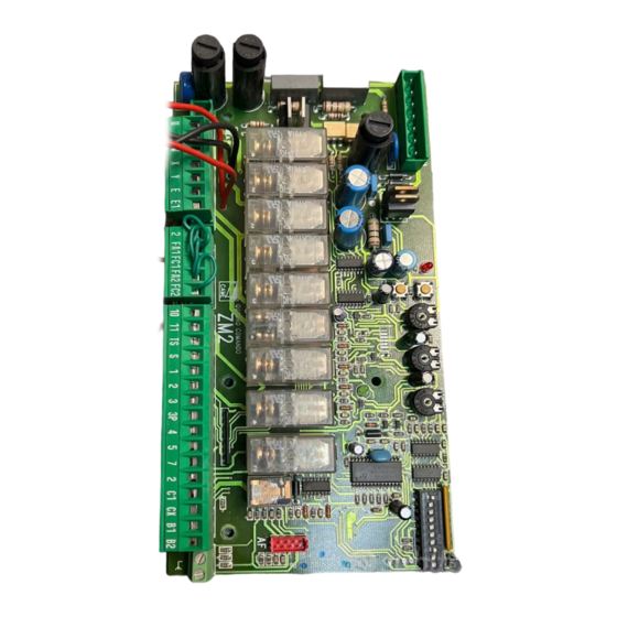
CAME Z Series Instrukcja instalacji
"CAUTION: IMPROPER INSTALLATION MAY CAUSE SERIOUS DAMAGE, FOLLOW ALL INSTALLATION INSTRUCTIONS CAREFULLY"
"THIS MANUAL IS ONLY FOR PROFESSIONAL INSTALLERS OR QUALIFIED PERSONS"
1 Legend
This symbol indicates sections to be read with particular care.
This symbol indicates sections concernig safety.
This symbol indicates notes to communicate to users.
2 Destination and limits of use
2.1 Intended use
The ZA2S control panel has been engineered to control the SUPERFROG automations, to operate swing doors.
The use of this product for purposes other than as described above and installation executed in a manner other than
as instructed in this technical manual are prohibited.
2.2 Limits to use
- Make sure the distances and cable diameters are as shown in the table at chapter 5.4.
- The overall power of the motors must not exceed 1200W.

3 Reference standards

This product complies with the following standards: EN 12978, UNI EN 954-1, CEI EN 60335-1, UNI EN 12453.
4 Description
The control panel is powered by 230/400V a.c. triphase through the R-S-T-N terminals, with 50/60Hz frequency.
The command devices and accessories run on 24V. Moreover, the total accessories cannot run on more than 40W.
A 12V electric-lock can connected to the system.
The control panel automatically controls the following functions:
1) automatic closing (adjustable);
2) working cycle (adjustable);
3) open-close or only opening command;
4) Reopening during the closing phase, re-closing during the opening phase or partial stop;
5) Maintained action (on the card, cut the spot marked with the £ symbol);
6) pre-flashing upon opening and closing;
7) obstruction detection when motor is not running;
8) Delaying the opening of the 1st gate leaf and during closing of the 2nd leaf (the latter is adjustable).
Protection
Low-tension
4.1 Technical specifications
Power Supply: 230/400V A.C. 50/60Hz tri-phase
Power draw when idle: 100mA
Max Power for accessories 12V: 15W
Max Power for accessories 24V: 30W
Max Power for accessories 230V: 30W
2
"IMPORTANT SAFETY INSTRUCTIONS FOR INSTALLATION"
FUSE
Fuse type
2A
Protection level: IP54
Weight: 6.2 kg
Insulation class:
Material: ABS