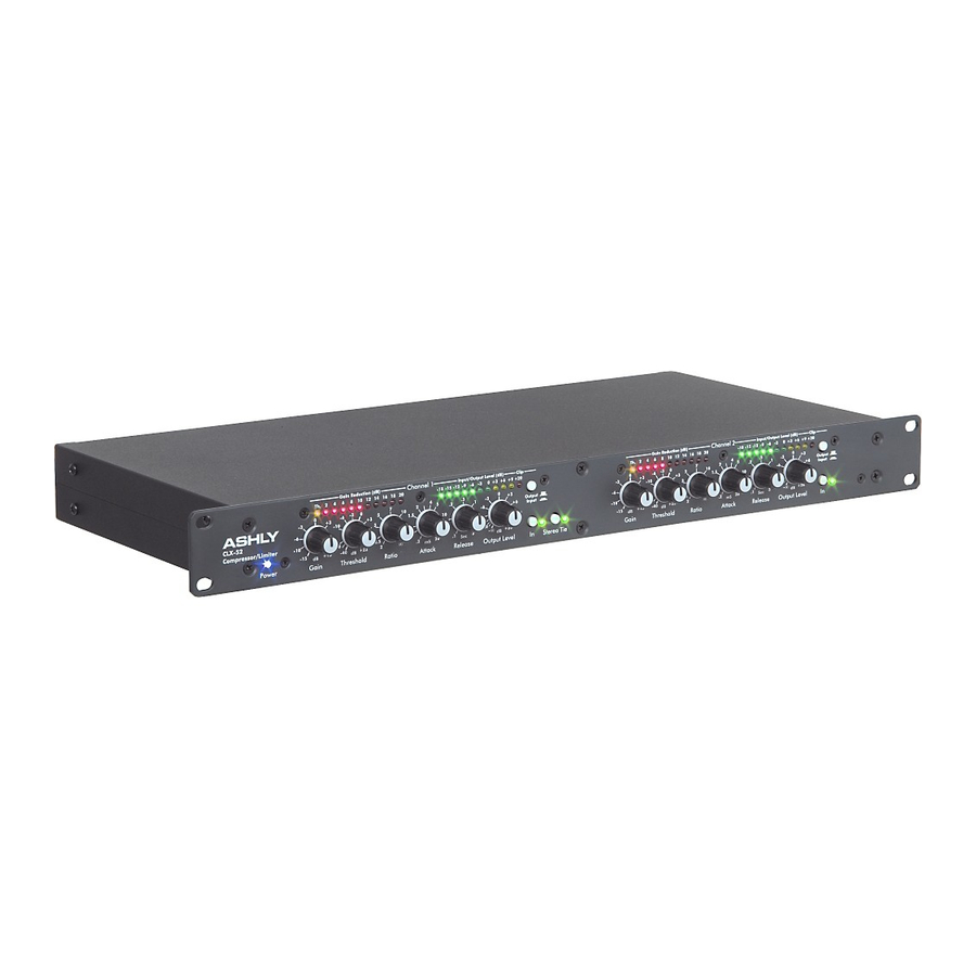
Ashly CLX-52 Instrukcja obsługi - Strona 9
Przeglądaj online lub pobierz pdf Instrukcja obsługi dla Sprzęt muzyczny Ashly CLX-52. Ashly CLX-52 12 stron. Compressor/limiter
Również dla Ashly CLX-52: Uwagi techniczne i specyfikacje (2 strony), Uwagi techniczne i specyfikacje (2 strony), Instrukcja obsługi (12 strony)

Operator Manual – CLX-52 Compressor/Limiter
Troubleshooting
Situation
No Audio Output
Controls Have No Effect
When Using Heavy
Compression,
Background Noise is
Noticeable During Quiet
Sections Of The Program
Excessive Hum or Noise
Note: Unshielded cables, improperly wired connections, and cable with broken strands
(shorts, etc.) are the most common problems. Use good quality cable with connectors
soldered firmly on the correct pin. When in doubt, get in touch with your Ashly dealer.
Dimensions
Inches (mm)
Action
Check AC power - is the power LED on?
Check in/out connections - are they reversed?
Are you sure you have an input signal?
Is the Limiter In/Out switch In? Perhaps the Ratio control is set too low to produce an audible
effect or the input level is below threshold. Is the Threshold LED lighting up? If not, lower the
threshold setting or increase the gain. Do not expect to hear any effect when the input level
is below threshold, since the unit is simply a linear amplifier at those levels.
Quiet program material is effectively made louder while loud peaks are made quieter. When
the program source is thus raised in volume, its noise floor is also raised in volume by a
proportionate amount. This is not a defect in the Compressor/Limiter, but an unavoidable
side effect of the gain altering process. If the noise becomes a problem, the solutions are to
either decrease noise at the program source, or use less compression.
Hum is often caused by a "ground loop" between components. Try using the suggested
balanced input and output hookups if the other pieces of equipment used in conjunction with
the CLX unit have balanced inputs and outputs. Noise can also be caused by insufficient
drive levels. Make sure you are sending a nominal 0 dBV line level signal to the unit.
All Rights Reserved
Page - 9
Introduction - 4
GQX Equalizers – 5
Connectors & Cables – 5
Physical Description - 6
Installation – 7
Typical Applications - 8
Troubleshooting - 9
Dimensions - 9
Specifications - 10
Warranty - 11
