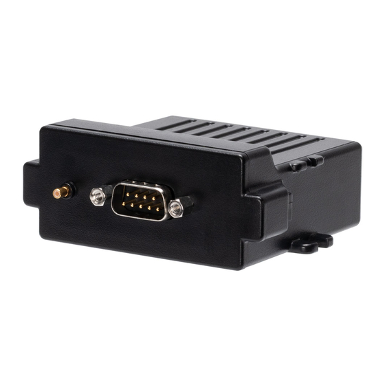
astra telematics AT210 Manual do utilizador - Página 8
Procurar online ou descarregar pdf Manual do utilizador para GPS astra telematics AT210. astra telematics AT210 9 páginas. Vehicle tracking device
Também para astra telematics AT210: Manual de instalação (5 páginas), Manual de início rápido (4 páginas)

Interconnections
All connections to the AT210 are provided by a single DB9 cable assembly.
AT210 Pin Applications and Colour Code
Pin
Function
1
VIN 7 - 36 VDC
2
RS232-TX1
3
RS232-RX1
4
DIG-OUT1
5
GND
6
DIG-OUT2
7
DIG-IN1
8
DIG-IN2
9
IBUTTON
Digital Inputs
Digital inputs 1 and 2 are normally-low and can be connected directly to 12/24V vehicle
circuits (i.e. power take off).
Digital Outputs
The AT210 is capable of switching two external loads of up to 30V, 0.5A using MOSFET
low side switches, which must be used to switch the GND side of the load. The use of a
1A in-line fuse with these switches is essential to prevent any damage through fault
scenarios.
Integrated Accelerometer
The AT210 has a built in 3 axis MEMS accelerometer that operates in the range ±2g and
is used to measure driver behaviour (acceleration and braking) during normal driving
conditions.
The accelerometer also allows the AT210 to wake from sleep on movement, with
configurable thresholds. Please refer to the $MEMS parameter for more details.
iButton (Dallas Key) Interface
This can be used to read iButton devices for the purpose of Driver Identification. See
the Driver ID Application Note for more details of how to use this feature.
Configuration
The AT210 shares a common set of configuration commands with our other devices.
Please refer to our Generic Device Configuration Reference for details.
Wire colour
red
green
blue
yellow
black
pink
white
brown
grey
