astra telematics AT210 Manual do utilizador - Página 6
Procurar online ou descarregar pdf Manual do utilizador para GPS astra telematics AT210. astra telematics AT210 9 páginas. Vehicle tracking device
Também para astra telematics AT210: Manual de instalação (5 páginas), Manual de início rápido (4 páginas)

SIM installation
Note that the AT210 powers up when the SIM is fitted
Basic electrical connections
A permanent connection to +12V/+24V vehicle power should be provided to the AT210
using the RED and BLACK wires, via a 1A fuse. If using a wired ignition-sense, connect
this to digital input 1, again we recommend the use of a 1A fuse:
i. RED
ii. BLACK
iii. WHITE
All unused wires should be insulated to avoid undesired behaviour.
For a full table of AT210 connections please see page 8.
Power requirements
The AT210 operates from a DC Voltage between 6 and 36 Volts. We recommend that a
permanent 'live' power source is used to supply the AT210. If current drain is of
concern, please see the power-down option of the $IGNM command, which can be used
to minimise battery drain when vehicles may be stationary for long periods.
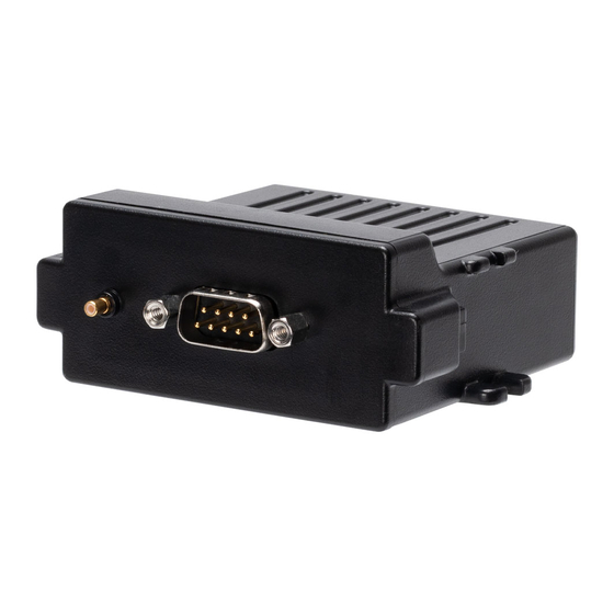
External GNSS antenna (optional)
The AT210 has an internal GNSS antenna, so an external antenna is not required in
most cases, but if the device is mounted in a location with poor sky visibility, an
external antenna can be used. If this is required, remove the cover from the GNSS
antenna connector (adjacent to the DB9) and plug in the AE004 GNSS active patch
antenna.
Notched corner here
+12 / +24V 1A FUSED
GROUND
1A FUSED
IGNITION
1A FUSED
External GNSS antenna connection
