bolid S2000-KPB Manual de instruções - Página 13
Procurar online ou descarregar pdf Manual de instruções para Unidade de controlo bolid S2000-KPB. bolid S2000-KPB 14 páginas. Executive module
Também para bolid S2000-KPB: Manual de instruções (17 páginas)
5.3.7 Switch on the battery backed power supplies connected to the module or connect power
circuits to the contacts "+Umain" and "+Uback".
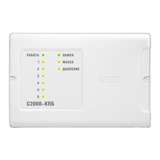
5.3.8 Ensure the module is in Quiescent Mode as the indicator shows. READY LED shall be lit
steady, COM LED shall be lit steady or flash, indicators of outputs shall indicate the initial status of
their control programs (see Table 2), MASS and PRESS LEDs shall operate in accordance with the
programmed configuration of the alarm loops (see Table 1).
5.3.9 Generate a command or event to activate control programs for each executive output.
5.3.10 Ensure the executive devices connected to the module respond (or light diodes of the
simulators turns on in accordance with the given programs).
5.3.11 Ensure that indicators "1" to "6" double operation of the control program for each output.
5.3.12 One-by-one simulate a short circuit failure of the circuit of the used output "1", "2", "3",
"4", "5", "6" of the module for which the module's configuration specifies the function of monitoring
short circuit failures.
5.3.13 Ensure that on closing the circuit the relevant output status indicator flashes in yellow once
per two seconds.
5.3.14 Ensure that the control device (the network controller) displays the event of short circuit
failure for the relevant device.
5.3.15 One-by-one, simulate open circuit failures for the used outputs "1", "2", "3", "4", "5', "6"
of the module for which the module's configuration specifies the function of monitoring open circuit
failures.
5.3.16 Ensure that on opening the circuit the status indicator of the relevant output double flashes
in yellow once per two seconds.
5.3.17 Ensure that the control device (the network controller) displays the event of open circuit
failure for the relevant device.
5.3.18 One-by-one, connect to the "loop 1" and "loop 2" terminals the resistors nominal values of
which are defined in the configuration of the S2000-KPB.
5.3.19 Ensure that the control device (the network controller) displays the events which
correspond to each resistance value and MASS and PRES indicators operate as shown in Table 1.
5.3.20 Switch off the battery backed power supplies connected to the module or disconnect the
power circuits from the contacts "+Umain" and "+Uback".
5.3.21 Connect the circuits at the outputs of the S2000-KDL module as specified by the design
documentation.
5.3.22 Switch on the battery backed power supplies connected to the module or connect the power
circuits to the contacts «+Umain» and «+Uback».
5.3.23 Close the cover of the module and seal if necessary.
5.3.24 Ensure the module LEDs indicates the module's being in Quiescent Mode. READY LED
shall be lit steady, COM LED shall be lit steady or flash, indicators of outputs shall indicate the initial
status of the control program (Table 2), MASS and PRESS LEDs shall operate in accordance with the
programmed configuration of the alarm loops (Table 1).
13