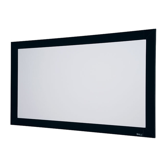
Draper Onyx Instruções de montagem - Página 2
Procurar online ou descarregar pdf Instruções de montagem para Ecrã de projeção Draper Onyx. Draper Onyx 2 páginas. Permanently tensioned projection screen
Também para Draper Onyx: Instruções de montagem (2 páginas), Instruções de montagem (2 páginas)

Onyx by Draper
Surface Preparation
➀ Move frame assembly out of the way, unroll viewing surface and place
on smooth/clean surface. (Orient viewing surface so that folded side of hem
is visible.)
➁ Insert plastic tubing inside pocket formed by hem on all 4 edges of viewing
surface (see Fig. 6).
➂ Slide surface retention extrusion (rounded edge visible) along hem and
onto surface on all 4 edges of fabric (see Fig. 7).
Please Note: To make this step easier, pinch the end of the pocket closed
before sliding it into the surface retention extrusion.
Surface Retention
Extrusion
Plastic Tubing
Back of
Viewing Surface
➃ Surface retention extrusion should extend beyond edge of viewing surface
equally at both ends.
➄ Verify that all surface retention extrusions are installed with rounded edge
visible and are centered on surface material.
Surface to Frame Assembly
➀ Return frame onto clean surface, face down, and drape completed surface
assembly over completed frame profile with rounded edge of surface
retention extrusion visible.
➁ Insert any side of surface to notch #1 on corresponding side of frame
extrusion (see Fig. 8).
Surface
Retention
Extrusion
Viewing
Surface
Fabric Attachment Extrusions
➂ Insert opposite side of surface to notch #1 of frame extrusion.
➃ Repeat steps 2-3 with remaining edges of surface.
➄ Ensure surface retention extrusions are centered lengthwise in tension
slots on all 4 edges of surface.
➅ If additional tension is desired or required over time, adjust surface one
edge at a time to tension notch #2.
Please Note: It is not necessary to adjust more than one edge at a time to
increase surface tension.
Figure 6
Back of
Viewing Surface
Figure 7
Figure 8
Mounting Screen to Wall
➀ Determine height at which screen is to be mounted.
Please Note: Top edge of screen frame will be located 1.5"above mounting
bracket hole centerline when mounted to wall.
➁ Mark hole centerline so that both Z-brackets can be mounted parallel and
at equal height.
➂ Install Z-brackets so that the outermost edges are safely within the overall
length of the aluminum frame extrusion to allow for minor horizontal screen
adjustments.
➃ Position screen slightly above Z-brackets on wall (see Fig. 9).
Z-brackets and
lag screws
supplied with
screen. Installer is
responsible for
ensuring appropriate
hardware is used.
Wall
➄ Lower screen until it engages over Z-brackets. Center screen horizontally
on brackets as necessary.
Please Note: Make sure screen is installed level.
Onyx Frame—Side Detail*
*Viewing surface is approximately ¼" from wall.
Onyx (Exploded Rear View)
Page 2 of 2
Figure 9
5
1
/
"
8
