Bosch 800 Series Manual de instalação - Página 7

Procurar online ou descarregar pdf Manual de instalação para Forno Bosch 800 Series. Bosch 800 Series 40 páginas. Built-in wall ovens
Também para Bosch 800 Series: Manual de instruções de instalação (24 páginas), Manual de instalação (40 páginas), Manual de utilização e cuidados (12 páginas), Manual de instalação (23 páginas), Manual de instalação (28 páginas), Manual de instalação (32 páginas), Manual de instruções (32 páginas), Manual de instalação (32 páginas), Manual de início rápido e de segurança (7 páginas), Manual de utilização e cuidados (40 páginas), Manual de instalação (32 páginas), Manual de instruções de instalação (40 páginas), Manual de instalação (48 páginas), Manual de utilização e cuidados (33 páginas), Manual de utilização e cuidados (49 páginas), Manual de início rápido (7 páginas), Manual de início rápido e de segurança (13 páginas), Manual de instalação (32 páginas), Manual de serviço (36 páginas), Manual de instruções de instalação (29 páginas), Manual de utilização e cuidados (24 páginas), Manual de utilização e cuidados (40 páginas), Manual de instruções de instalação (28 páginas)
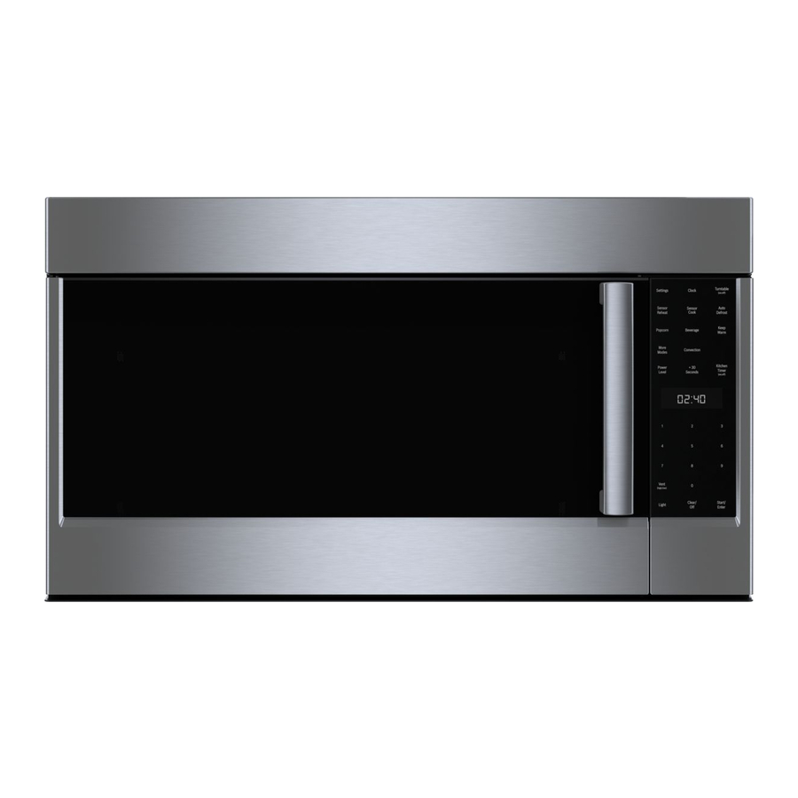
Bosch 800 Series Manual de instalação

Step 2 - Replace the orifices

WARNING
9
To prevent burns, do not touch grates, burner caps
or burners while hot. Turn the cooktop off and allow
the burners to cool.
Remove the grates and burner caps and burners.
1.
Remove the orifices.
2.
Notes
The orifices require a 7 mm socket driver for
removal/replacement. The driver will need to be
inserted approximately 2
cavity to reach the orifice.
To reduce the chance of the orifice being dropped
from the socket driver, add a piece of foam tape or
adhesive tape inside the socket.
Trim a small piece of the foam tape provided
A
with this kit (about
Fit this so the tape wraps against one side of
B
the socket so it stays in place.
The tape will fit to the orifice and help prevent
C
the orifice from falling out of the socket during
extraction.
Save the NG orifices in case there is need later to
restore the appliance to use natural gas again.
^
" (64 mm) into the burner
" x
" / 6 mm x 12 mm)
]
^
Identify the correct placement of the LP gas orifices as
3.
detailed in the Before You Begin chapter.
Note: The NGMP056UC and NGMP656UC models
have a second orifice that will be visible after the
center burner is removed. This orifice must also be
changed during the conversion to use LP gas.
Smaller center orifice
A
The LP gas orifice sizes corresponding to each burner
are shown in the following images. These numbers are
engraved on either the top or the side of each orifice. It
is very important to install the correct orifice size for
each burner.
7