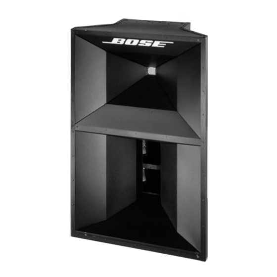
Bose PANARAY LT 3202 II Manual de serviço - Página 11
Procurar online ou descarregar pdf Manual de serviço para Sistema de altifalantes Bose PANARAY LT 3202 II. Bose PANARAY LT 3202 II 18 páginas.

DISASSEMBLY/ASSEMBLY PROCEDURES
Caution: The rear of the Panaray
loudspeakers can become extremely hot
during normal use. Do not attempt to
service the loudspeakers until they have
cooled to room temperature.
Note: Numbers in parentheses correspond
to the item call outs in Figure 2.
1. Compression Driver Removal
1.1 Disconnect the Neutrik Speakon™
connector from the connector panel (6).
1.2 Remove the two screws (7) holding the
cover assembly on to the cabinet. Slide the
cover assembly (15) up and remove it from
the cabinet.
1.3 Disconnect the red and black wires
from the terminals of the compression
driver (1).
Note: On some models, the connectors
may have been soldered.
1.4 Remove the four screws (4) holding
the compression driver assembly (1) to the
cabinet.
1.5 Remove the compression driver as-
sembly from the cabinet.
1.6 Remove the four screws holding the
compression driver to the mounting plate
(3).
2. Compression Driver Replacement
2.1 Place the new driver on to the mount-
ing plate (3) and secure it to the plate.
2.2 Place the compression driver assembly
(1) into the cabinet and secure it to the
cabinet.
3202™/4402™/9702™ SERIES II
®
LT
11
2.3 Reconnect the red and black wires
on the compression driver terminals.
Take care to place the red wire on the
positive(+) terminal and the black wire
on the negative (-) terminal.
2.4 Perform the test procedures on page
13.
2.5 Align the cover assembly (15) tabs
with the slots in the cabinet and slide the
cover into place. Secure the cover to the
cabinet.
2.6 Reconnect the Neutrik Speakon
connector to the connector panel.
3. Vee Four Driver Removal
3.1 Perform steps 1.1 and 1.2.
3.2 Disconnect the green and white wires
from the Vee Four terminals.
3.3 Remove the four screws (5) holding
the Vee Four driver assembly (2) to the
cabinet.
3.4 Remove the Vee Four driver assembly
(2) from the cabinet.
4. Vee Four Driver Replacement
4.1 Place the new Vee Four driver assem-
bly into the cabinet.
4.2 Secure the driver assembly (2) to the
cabinet using the screws supplied with the
new driver assembly package.
4.3 Reconnect the green and white wires
to the terminals on the driver assembly.
Take care to place the green wire on to the
positive (+) terminal and the white wire on
to the negative (-) terminal.
4.4 Perform steps 2.4 thru 2.6.
