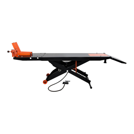
APlusLift MT1500X Manual de instalação e instruções de funcionamento - Página 14
Procurar online ou descarregar pdf Manual de instalação e instruções de funcionamento para Sistemas de elevação APlusLift MT1500X. APlusLift MT1500X 20 páginas. Motorcycle lift

I nst a lla t ion
4 .
4.6 SIDE EXTENSION INSTALLATION ( APlusLift MT1500X)
The side extensions for the APlusLift MT1500X are easily installed. There are 4 extension tubes
provided for installation which also includes 1 stabilizing bar. The 2 short extension tubes are
slid into the holes on the back of the table assembly at the opposite end of the vise by the rear
approach ramp. You must secure the short extension tubes to the table assembly by
securing and tightening 1 screw in each tube under the table to lock them in place once they
are installed. The long extension tubes run all the way through, underneath the front side of
the table assembly and also in front of the drop out tail on some models.
You must remove both end caps, slide the stabilizer bar through the square holes on the rear
locking scissor legs and then reattach the end caps to the stabilizer bar. Slide the 2 extensions or
tool trays over the tubes and insert the quick pins in the appropriate holes at the end of the round
tubes to secure the table extensions to the lift. For the approach ramp, use the provided bolts and
nuts to secure the ramp extensions onto the approach ramp on each side.
Please see the pictures below for proper installation of the side extensions & tool trays.
NOTE: ALWAYS ensure that the load lifted is on the center line of the table in line with the
center of the front vise and the rear drop out tail.
2 Long Extension Bars
NOTE: YOU CAN INSTALL
THE SIDE EXTENSIONS
TURNED 180
THEM AS TOOL TRAYS!
Copyright
2020
C
2 Short Extension Bars
O
AND USE
TM
Phone: 800-616-9618 Text: 425-300-2600 Email: [email protected]
www.apluslift.com
APlusLift MT1500 & MT1500X
I N ST ALLAT I ON M a nua l
6 Quick Pins
SAFET Y LOCK
LAT CH BAR
14 of 20
