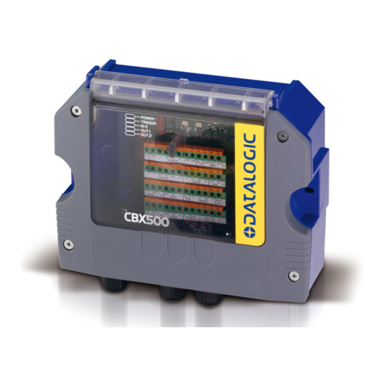
Datalogic CBX500 Manual de instalação - Página 12
Procurar online ou descarregar pdf Manual de instalação para Leitor de código de barras Datalogic CBX500. Datalogic CBX500 17 páginas. Scanning connection box
Também para Datalogic CBX500: Manual de instalação (16 páginas), Manual de instalação (17 páginas)

CBX500 INSTALLATION MANUAL
CHASSIS GROUNDING JUMPER SETTINGS
The reading device chassis grounding method can be selected by positioning a jumper (see
Figure 8). In this way the reading device chassis can be connected to earth ground (only if
pin Earth is connected to a good earth ground). For all reading devices except 6K/8K, the
chassis can alternatively be connected to the power supply ground signal (GND) or it can be
left floating but, in this case, the jumper must be removed. For 6K or 8K scanners the chassis
is internally connected to GND.
All Reading Devices (except 6K/8K)
to GND
The scanner chassis is
internally connected to GND
6K, 8K Family Scanners
9-PIN READING DEVICE AUXILIARY SERIAL INTERFACE
The reading device auxiliary serial interface available on the internal CBX500 9-pin
connector can be used either for configuration or for data monitoring.
Connections can be made to a PC or Laptop using a straight through cable or a USB-RS232
converter.
The details of the connector pins are indicated in the following table:
Pin
2
3
5
1, 4, 6, 7, 8, 9
12
floating
to Earth (default)
to Earth (default)
Figure 8 – Chassis Grounding
5
9
Figure 9 - 9-pin D-Sub Female Connector
9-pin Connector Pinout
Name
Function
TX
Auxiliary RS232
RX
Auxiliary RS232
SGND
Auxiliary Reference Ground
N.C.
1
6
