GAC LSM201 Manual - Página 6
Procurar online ou descarregar pdf Manual para Controlador GAC LSM201. GAC LSM201 11 páginas. Load sharing modules
5
INITIAL ADjUSTMENTS (CONTINUED)
vOltAGE SiGNAl: ANALOG POwER OuTPuT SIGNAL, INTERNAL ANd ExTERNAL METERING
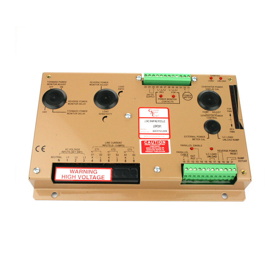
The voltage signal at Terminals 32 (+) and 33(-) may be adjusted with the EXTERNAL POWER METER
CAL adjustment, and has a range of approximately -1 to 5 V DC. These voltages are proportional to the CT
currents. An output of 5V indicates 5 A CT current (forward power) and -1 volt will indicate 1 A CT current
(reverse power). Terminal 32 maximum current consumption should be limited to 10 mA.
The Internal Power Meter / Bar graph displays the generator power in the external power meter operation.
The bar graph can be calibrated for generator power. The display normally shows the zero power output
position with no power, or with full power to the applied to the generator it displays the third dot. Adjust the
GENERATOR POWER DISPLAY CAL for a full-scale reading. Be sure that the adjustment is made by moving CW from
the zero position.
FORWARD POWER MONitOR
The forward power monitor can signal two levels of power output from the generator. The two trip points are:
•
ON where power is increasing and exceeds the monitors high limit set point. ON range is from 20-100% power which corresponds
to a 0-80 on the adjustment scale.
•
OFF when the power is falling below the monitors lower load limit set point. OFF range is from 0-80%
power which corresponds to 0-100 on the adjustment scale.
•
If the maximum CT currents are less than 5 A, the adjustment range will exceed these power levels.
The monitor also includes a DELAY adjustment. In the full CCW position (0) the delay is very short, about 0.4
seconds. In the full CW position (100), the delay is about 30 s.
An internal relay with 10 A Form C contacts normally open (NO) and normally closed (NC) are included at Ter-
minals 28, 29, and 30 along with an LED to signal the monitor relay status.
1.
Always set the ON point first with the delay set to minimum delay. With the ON adjustment at a setting of 80, adjust the generator
load for a desired trip point, i.e. 90% load. Turn the ON adjustment CCW until the monitor turns on with 90% load applied.
2.
With the OFF adjustment at a setting of 0, adjust the generator load for a desired reset point, i.e. 20% load. Adjust the OFF
adjustment CW until the monitor resets to OFF with the load reduced to 20%.
3.
Adjust the monitor's DELAY setting. The Full CCW position offers minimum delay (about 0.4 seconds) and the Full CW position
offers a delay of about 30 seconds. These are inverse time delays as in the reverse power circuits.
PROGRAMMABilitY
Once the ON and OFF adjustment have been set, they can be externally programmed with an analog DC signal at Terminal 22. If
this terminal is connected to signal ground, it will lower the set point of the monitors approximately 20%. Raising the voltage at Termi-
nal 22 above the nominal 3 V will increase the set points to a level higher than the internal settings. Consult GAC for details.
REvERSE POWER MONitOR
use care when setting the Reverse Power delay so excessive delay does not damage the generator or
switch gear.
do Not disconnect the CT's while the engine is running.
LSM200 Series monitors forward and reverse power output of the generator. The reverse power relay signals if the generator's power
has gone negative. If negative power exists above a small level, the generator must be removed from service. Reverse power relay
contacts are Terminals 25-27.
The set point is adjustable between 2 % and 20 % based on a 5 A CT rating at 100 % power, where 0 is the most sensitive and 100 is
about 20 % reverse power, the highest setting.
NOtE: The reverse power monitor circuit must have a jumper wire or a reverse power reset switch across Termi-
nals 18 and 19. The Reverse Power reset jumper or switch must be in p/ace at Terminals 18 & 19 for this monitor
to function.
Latching and non-latching operation of the Reverse Power monitor relay signal is supported. Factory defaults
are set to non-latching configuration which, when a reverse power condition above the set point takes place, the
reverse power relay activates. When the reverse power condition reduces or disappears, the monitor automatically resets.
If a latching condition for the reverse power monitor is required, connect E1 and E2 together. These posts are located on the circuit
board just above and to the right of the AC Voltage Selector DIP Switch. On the LSM201N module, these posts are located on the
circuit board just above the AC Voltage Selector DIP Switch.
LSM200 Series Load Sharing Modules 6-2021-B1 PIB4100
6
Governors America Corp. © 2021 Copyright All Rights Reserved