GAC LSM201 Manual - Página 8
Procurar online ou descarregar pdf Manual para Controlador GAC LSM201. GAC LSM201 11 páginas. Load sharing modules
6
BEFORE STARTING ThE ENGINE
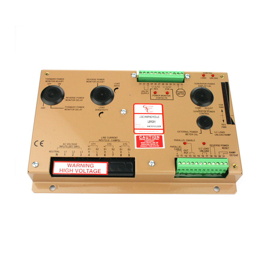
LETHAL HIGH VOLTAGE is present at Terminals 1, 2, & 3. do not disconnect the CT wiring (Terminals
4, 5, 6, 7, 8, 9) when the generator is operating.
Once the LSM200 Series is connected into the system per the appropriate wiring diagram, the following adjustments can be made in
the following order.
1.
Pre-checks
2.
Current transformer phasing
3.
load sharing adjustment
4.
Load anticipation adjustment
5.
Reverse power adjustment
6.
Forward power Monitor adjustment
7.
Power meter operation
PRE-CHECKS
The following pre-checks must be made before starting engine:
1.
With the Reverse Power reset jumper or switch in place at Terminals 18 & 19, set the following:
ADjUStMENt
Reverse Power
Reverse Power Relay
Forward Power "On"
Forward Power "OFF"
Forward Power Delay
Load Sensitivity
Load Anticipation
External Power Meter Cal
ILC Load Ramp
Generator Power Ramp
Generator Power Adjust
Generator Power Display Cal
2.
Measure the following voltages at these terminals in this order with DC power applied to the unit.
tERMiNAl
31 (+) to 23 (-)
Internal Power Supply
12 (+) to 23 (-)
Output to Governor
3.
Apply AC voltages to unit (run engine at no load)
tERMiNAl
TPI1 (+) to TP2 (-)
32 (+) to 33 (-)
CURRENt tRANSFORMER PHASiNG
Test for Phasing:
1.
With a DC meter across TP1 (+) and TP2 (-), apply a small amount of load to the generator and note the voltage reading and polarity.
2.
With a large gauge jumper wire, short out each CT signal (Terminals 4 to 5, 6 to 7, 8 to 9) one at a time.
3.
If the short is of low resistance, a 1/3 drop in voltage at the test points will be measured.
4.
If the drop is not near 1/3 or the voltage increases, the CT / AC line voltage phasing is improper and must be corrected in the wiring.
POSitiON
10
Full CCW
80
100
Full CCW
100
0
100
20
0
0
50
vOltAGE MEASUREMENt
vOltAGE MEASUREMENt
Generator Power Signal
Internal Power Meter
SEttiNG
Approx. 5%
Fastest
100%
0%
Fastest
Most Sensitive
0
Max. Range
Approx. 4 Sec.
0
0
5 Amps = Full Scale
vAlUE
10.6 ± 0.2 V DC
5.0 ± 0.1 V DC
vAlUE
0 ± 0.2 V DC
0 ± 0.2 V DC
LSM200 Series Load Sharing Modules 6-2021-B1 PIB4100
8
Governors America Corp. © 2021 Copyright All Rights Reserved