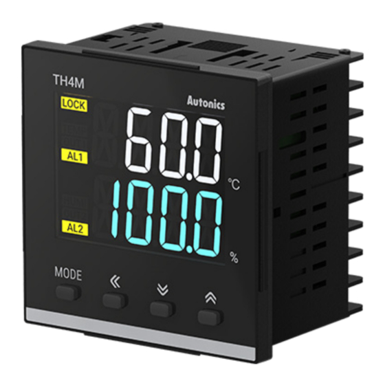
Autonics TH4M Series Manual do produto - Página 2
Procurar online ou descarregar pdf Manual do produto para Controlador de temperatura Autonics TH4M Series. Autonics TH4M Series 4 páginas. Lcd temperature/humidity controllers

• Install a power switch or circuit breaker in the easily accessible place for supplying or
disconnecting the power.
• Do not use the unit for other purpose (e.g. voltmeter, ammeter), but temperature/
humidity controller.
• When changing the input sensor, turn off the power first before changing. After changing
the input sensor, modify the value of the corresponding parameter.
• Make a required space around the unit for radiation of heat. For accurate temperature
measurement, warm up the unit over 20 min after turning on the power.
• Make sure that power supply voltage reaches to the rated voltage within 2 sec after
supplying power.
• Do not wire to terminals which are not used.
• This unit may be used in the following environments.
- Indoors (in the environment condition rated in 'Specifications')
- Altitude Max. 2,000 m
- Pollution degree 2
- Installation category II
Product Components
• Product
• Bracket
Sold Separately
• Terminal protection cover: RMA Cover
Specifications
Model
TH4M-24R
Power supply
100 - 240 VACᜠ 50/60 Hz ±10%
Power consumption
≤ 8 VA
Sampling period
1 sec
• At room temperature (25 ℃ ±5 ℃): ≤ ±1.0 ℃
Temperature
• Out of room temperature range: ≤ ±2.0 ℃
Display
• At room temperature (25 ℃ ±5 ℃): ≤ ±3.0%RH (20 to 90%RH ),
accuracy
Humidity
• Out of room temperature: ≤ ±5.0%RH (all range)
Display
Temperature -20.0 to 60.0 ℃
range
Humidity
10.0 to 100.0%RH
Temperature -20.0 to 60.0 ℃
Using
range
Humidity
10.0 to 100.0%RH
Temperature
Relay: 250 VACᜠ 3 A, 30 VDCᜡ 3 A, 1a
(OUT1)
Control
output
Humidity
01)
Relay: 250 VACᜠ 3 A, 30 VDCᜡ 3 A, 1a
(OUT2)
Alarm
Relay
AL1/2: 250 VACᜠ 3 A, 1a
output
11-Segment (temperature: white, humidity: blue), other display
Display type
02)
(yellow) LCD type
Control type
ON/OFF control
Relay life
Mechanical
≥ 5,000,000 operations
cycle
Electrical
≥ 200,000 operations (resistance load: 250 VACᜠ 3 A)
Between primary circuit and secondary circuit: 3,000 VACᜠ 50/60
Dielectric strength
Hz for 1 min
0.75 mm amplitude at frequency 5 to 55Hz (for 1 min) in each X, Y, Z
Vibration
direction for 2 hours
Insulation resistance
≥ 100 MΩ (500 VDCᜡ megger)
±2 kV square shaped noise (pulse width 1 ㎲) by noise simulator
Noise immunity
R-phase, S-phase
Memory retention
≈ 10 years (non-volatile semiconductor memory type)
Ambient temperature
-10 to 50 ℃, storage: -20 to 60 ℃ (no freezing or condensation)
Ambient humidity
35 to 85%RH, storage: 35 to 85%RH (no freezing or condensation)
Double or reinforced insulation (mark: ▱, dielectric strength
Insulation type
between primary circuit and secondary circuit: 3 kV)
Approval
ᜢ
Unit weight
≈ 144 g
01) Connect to a load using the same power supply. Connecting to a load from a different power supply may
cause safety issues.
02) When using the unit at low temperature (below 0℃), display cycle is slow.
■ Temperature/Humidity sensor
Model
THD-RM
Power supply
3.3 VDC ±2%
Power consumption
≤ 1.3mA
Response time
15 sec
• At room temperature (25 ℃ ±5 ℃): ≤ ±1.0 ℃
Temperature
• Out of room temperature: ≤ ±2.0 ℃
Sensing
• At room temperature (25 ℃ ±5 ℃): ≤ ±3.0%RH (20 to 90%RH ),
accuracy
Humidity
• Out of room temperature: ≤ ±5.0%RH (all range)
Sensing
Temperature -20.0 to 60.0 ℃
range
Humidity
10.0 to 100.0%RH
Communication type
I2C communication output
Dielectric strength
Between primary circuit and case: 500 VACᜠ 50/60 Hz for 1 min
0.75 mm amplitude at frequency 5 to 55Hz (for 1 min) in each X, Y, Z
Vibration
direction for 2 hours
Ambient temperature
-20 to 60 ℃, storage: -20 to 60 ℃ (no freezing or condensation)
0 to 100%RH, storage: 35 to 85%RH (no freezing or condensation)
Ambient humidity
Cable
Ø4 mm, 4 seam , 2 m (tensile strength: 1kgf/s)
Approval
ᜢ
Unit weight
≈ 56 g
• Instruction manual
• Temperature/Humidity sensor THD-RM
≤ ±5.0%RH (below 20%RH,
over 90%RH)
≤ ±5.0%RH (below 20%RH,
over 90%RH)
Unit Descriptions
4
1
2
3
4. Indicator
Display
Name
Description
LOCK
Lock
Turns ON when lock function is activated (parameter)
TEMP
Temperature control
Turns ON when temperature control is ON
HUMI
Humidity control
Turns ON when humidity control is ON
OUT1/2
Control output
Turns ON when the control output is ON
AL1/2
Alarm output
Turns ON when the alarm output is ON
Errors
Indicator
Display
Temperature
Flashes OPEN
Humidity
Temperature Flashes HHHH
Humidity
Fixes maximum value
Temperature Flashes LLLL
Humidity
Fixes minimum value
Dimensions
• Unit: mm, For the detailed drawings, follow the Autonics website.
□72
■ Panel cut-out
≥ 90
68
+ 0.7
0
■ Temperature/Humidity sensor
36.6
13.1
2-Ø4.2
Ø4, 2m
25
1. Temperature display part (White)
Run mode: displays temperature PV (Present value)
•
Setting mode: displays parameter name
•
2. Humidity display part (Blue)
Run mode: displays humidity SV (Setting value)
•
Setting mode: displays parameter setting value
•
3. Input key
Display
Name
[MODE]
Mode key
[◀], [▼], [▲]
Setting value control key
Description
Trouble shooting
Flashes when input sensor is
Check input sensor
disconnected or sensor is not
status.
connected.
Flashes when measured value
When input is within
is higher than input range.
the rated input
range, this display
Flashes when measured value
disappears.
is lower than input range.
51
6
45
■ Bracket
46
12
23.9
15.1
