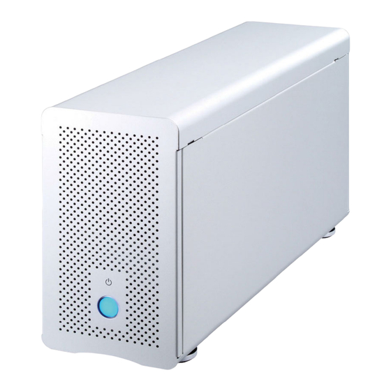
HighPoint Thunderbolt TurboBox NA211TB Manual de instalação rápida - Página 2
Procurar online ou descarregar pdf Manual de instalação rápida para Invólucro HighPoint Thunderbolt TurboBox NA211TB. HighPoint Thunderbolt TurboBox NA211TB 3 páginas. Expansion enclosure

Thunderbolt
1.
Overview
Based on the most up-to-date Thunderbolt
PCIe architecture, the revolutionary design of TurboBox NA211TB
allows different combinations of highP performance PCIe addP on
cards to be attached to any Thunderbolt
through the blazing fast 10Gbps Thunderbolt interface to meet
professionals' needs for any demanding configuration on
work. This quick installation guide will help you set up the
TM
Thunderbolt
TurboBox NA211TB.
2.
Package Checklist
Before installing this unit, verify the package contains the
following items.
B
TM
Thunderbolt
(2 meters) x 1
A
TurboBox x 1
D
User manual
CD x 1
Notify your sales representative if any of the above items is
missing or damaged.
3.
Panel Layout
1
2
5
TM
PCIe Expansion Enclosure
1. Power--on indicator LE
This power-on indicator LED only shows the status of power.
TM
technology and
When TurboBox is powered on, it shows blue. When TurboBox
is powered off, it shows no light.
2. Thunderbolt ports
TM
equipped computer
No specific Thunderbolt
the Thunderbolt
upstream device, the other port is connected to downstream
device.
3. PCIe expansion
4. Thumbscrew for loosening/tightening the top cover
5. Power cord receptacle
4.
PCIe Card Hardware Configuration
C
Power cord x 1
cable
E
Carry bag x 1
Slot1 : Thunderbolt
(already fixed inside the TurboBox)
Slot2 : PCIe x8 slot
(open-type;; supports PCIe card x1/x4/x8/x16)
Slot3 : PCIe x8 slot
(supports PCIe card x1/x4/x8)
Slot4 : PCIe x4 slot
(supports PCIe card x1/x4)
3
4
TM
port is appointedv when one of
TM
ports on NA211TB is connected to host or
inside
4 3 2 1
1 2 3 4
TM
target card
5.
Installation of PCIe Add-on Cards in
NA211TB
Before proceeding to installation procedure,
disconnect the NA211TB from power source for prevention
of electric shock or damage to PCIe add-on card.
1. Loosen the thumbscrew and remove the top cover of
NA211TB.
Step 1
2. Three PCIe slots on rear panel of NA211TB are
pre-covered by removable L-shape metal brackets.
Loosen the screw of the removable L-shape metal
bracket, and the installation of PCIe cards becomes
ready.
Step 2
3. Insert PCIe cards into proper PCIe slots of NA211TB
and tighten them with screws on brackets of PCIe
cards.
Step 3
