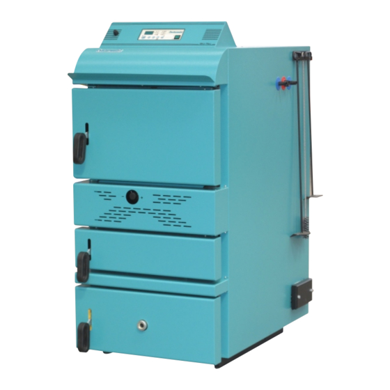
Centrometal Bio-Tec 25 Manual técnico - Página 14
Procurar online ou descarregar pdf Manual técnico para Caldeira Centrometal Bio-Tec 25. Centrometal Bio-Tec 25 17 páginas.

- 1. Technical Data
- 2. Delivery Package
- 3. Additional Equipment
- 4. Cleaning and Maintenance of the Boiler
- 5. Connection to the Chimney
- 6. Boiler Use
- 7. Connection to the Central Heating System
- 8. Boiler Start up
- 9. Boiler Thermal Protection
- 10. Thermal Fuse
- 11. Electric Connection
- 12. Boiler Regulation
Boiler thermal protection
5.2.1. BOILER THERMAL PROTECTION
According to European EN standards, boiler thermal protection must be installed in
closed heating system. Boiler is factory prepared for installation of thermal
protection. Heat exchanger is built into boiler at factory, and thermal safety valve 7
should be installed according to scheme 3. In case of any damage of boiler installed
in the closed heating system due to its overheating, and boiler or system are not
equipped with any thermal protection at all, or do not have properly installed thermal
protection, guarantee will not be applied.
IMPORTANT:
Thermal protection must be connected to the water supply installation of the
premises supplied from the water supply line and not from hydrophor. Namely, in
case of failure of power supply, boiler could be overheated, and then hydrophor is
not able to ensure required water supply.
THERMAL FUSE:
Thermal protection for boiler Bio-Tec consists of a heat exchanger which is factory
built in boiler, and thermal valve 7 (such as CALEFFI 543 513) (see Scheme 3.).
Part 7 is installed into prepared connector (male thread 3/4") in the upper part of
left lateral side of the boiler casing.
INSTALLATION (under Scheme 3.)
-
screw the thermal safety valve sensor 6 (outer thread1/2 ) into the sleeve joint 2
(inner thread1/2 ).
"
- fix the connection 4 (inner thread 3/4 ) of the thermal safety valve to the sanitary
cold water inlet and the connection 5 (inner thread 3/4 ) through the reduction to
the connection point of the heat exchanger 1 (outer thread1/2 ) - the arrow shows
the direction.
- fix the tube connected to the sewage outlet at the connecting point 3 (outer
thread1/2 ).
"
14
"
"
"
"
Technical manual Bio-Tec
By pressing two buttons simultaneously you can see different values:
Button ''P'' and buttons ''+'' or ''-'': display of measured values:
01 -
Measured boiler temperature.
02 -
Measured sanitary water temperature.
03 -
Measured room temperature.
04 -
Setup room temperature (reading from the room thermostat).
05 -
Measured upper temp. in the first accumulator tank (outlet).
06 -
Measured lower temp. in the last accumulator tank.
07 -
Measured flue gases temp. (display scale 5°C).
Button ''P'' and button ''GLOW'': setup parameter values:
1 -
Setup temperature sanitary water. Adjusting range 20-70°C.
2 - Sanitary water pump steering mode. 0=parallel functioning, 1=priority
sanitary water.
3 - Parameter which determines if sanitary hot water heater and sensor
are in configuration. 0=no hot water heater, 1= sanitary hot water
heater connected.
Other parameters are factory set and can not be changed.
Button ''P'' and main switch (0/1): back to the preset regulator mode.
Button ''GLOW'' and main switch (0/1): test relay regulator mode.
Detailed description of the digital regulation with single buttons or indications (LED
diods) is displayed in the Technical manual "Digital boiler regulation Bio-Tec".
8.0. ELECTRIC CONNECTION
All electrical works must be performed by a certified professional in accordance
with valid national and European standards.
A device for switching of all power supply poles must be installed in electrical
installation in accordance with the national regulations on electrical installations.
Detailed description of connecting the sensors and operation of digital regulation is
displayed in the Technical manual "Digital boiler regulation Bio-Tec".
Technical manual Bio-Tec
Boiler regulation
19
